 We’ve written several articles about speaker power ratings over the years, but the topic seems to be one that very few people understand fully. This article will serve as the reference guide for how premium and reputable manufacturers rate the power handling capabilities of their speakers. We’ll start by looking at the physics of speaker design regarding how they cope with the heat created by the power from your amp, then explain how pink noise is used to create power ratings.
Loudspeaker Efficiency and Power
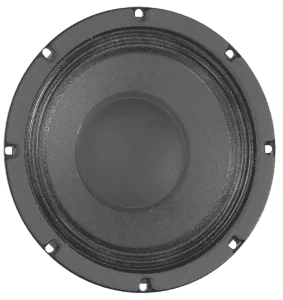 Unfortunately, loudspeakers are notoriously inefficient. A high-efficiency 8-inch midrange driver used in a public address speaker can only transform about 1.3 percent of the power from the amp into acoustic energy. The remainder is converted to heat in the voice coil and, subsequently, the parts around the coil such as the magnet, T-yoke and cone.
Speakers designed for car audio applications are often significantly less efficient because they need to operate over a wider frequency range. For a midrange driver with a sensitivity rating of 90 dB 1W/1M, the efficiency is a paltry 0.63 percent.
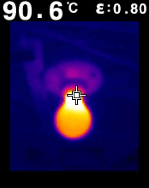
Think about how much heat a 100-watt incandescent light bulb generates. Below is a thermal image of a 100-watt bulb that has been turned on for only 60 seconds. The glass base of the bulb has already reached a temperature of more than 90 degrees Celsius or 195 degrees F. It’s clearly too hot to touch and will only continue to get hotter. Quick research shows that incandescent light bulbs have an efficiency of about 2.2. This lack of efficiency makes them a great analogy in terms of comparing heat generation to that of a loudspeaker. We’ll get into the logistics and reality of feeding that much power into anything but a subwoofer shortly.
How Speakers Handle Heat
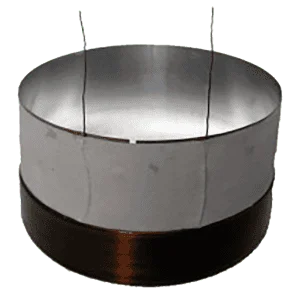 Heat in a speaker is generated in the voice coil winding. Whether it’s copper, aluminum or a combination of both, all that heat is focused on that relatively tiny coil of wire. The only component that comes into direct contact with the voice coil is, not surprisingly, the voice coil former. In car audio speakers, voice coil formers are made from materials such as kraft paper, synthetic insulating papers such as 3M TufQUIN, aramid fibers such as Nomex and Bondex, and aluminum. Each of these materials has different insulating and thermal conductivity properties.
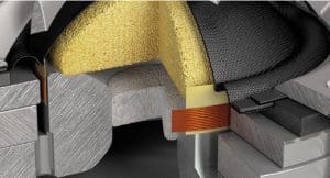
The next speaker component that has to handle the heat from the voice coil is the top plate. In most cases, the top plate is a piece of steel that is affixed to the magnet (or magnets) to focus the magnetic field on the voice coil. Though the top plate doesn’t come into contact with the voice coil, the two components are very close to each other. The majority of the cooling for the speaker’s voice coil can be attributed to heat being transferred away into the top plate and subsequently the motor structure. Many loudspeaker manufacturers go to great lengths to ensure there is significant airflow around the top plate to further enhance cooling, especially on subwoofers.
The T-yoke, the part of the motor structure that completes the magnetic field loop, is also important in helping to draw heat away from the voice coil and the former. The T-yoke resides inside the voice coil former in most designs.
Subwoofer Voice Coil Diameter and Power Handling
 The ability of any device to handle heat is determined by its size. A 1/8-watt resistor is much smaller than a 1-watt resistor. Generally, the size of a component determines the amount of surface area and the ability to transfer heat into the air. In speakers, the diameter and length of the voice coil winding in a subwoofer are a good indicator of how much heat and, subsequently, how much power the speaker can handle.
By way of an example, looking through a popular subwoofer manufacturer’s product range, we see that their subwoofers with a 2-inch diameter voice coil are rated for 250 watts; stepping up to a 2.5-inch diameter coil increases the power rating to 500 watts. Their subwoofers with 3-inch coils are rated at 600 watts, and their competition-level woofers have massive 4- and 5-inch diameter coils rated for 2,500 and 3,000 watts, respectively.
Keep in mind, the physical size (height) of each of these voice coils was not provided, so it’s safe to assume that the jump to more than 2,500 watts of power handling comes with a significant increase in coil winding height and associated surface area.
High-Frequency Speaker Voice Coil Sizes
Talking about power handling in anything but a subwoofer is going to require some common sense. Think carefully about the power handling ratings on a midrange speaker. We’ll look across another popular brand and see how their voice coil diameters relate to the power handling specifications of several of their 6.5-inch midrange speakers. This brand has a driver with a 1-inch coil rated for 70 watts, and a 1.25-inch coil is rated 80 watts in one series and 100 watts in a higher-end solution. The different power ratings on the 1.25-inch coils demonstrate how the overall height of the winding affects thermal capacity.
 Now, let’s talk about tweeters. Tweeters in car audio applications are extremely small and, frankly, quite fragile. The voice coil windings in tweeters are made from very fine wire, often smaller than 24 gauge. Even with a diameter of 1 inch on a soft-dome tweeter, they can’t handle much power. So, how do manufacturers come up with ratings of 100 watts or more for their tweeters when we know a midrange driver with a voice coil winding that’s at least five times as tall can only handle 100 watts? The answer lies in how manufacturers test their speakers.
What is Pink Noise?
Before we get into the explanation of how speaker power handling is rated, we need to take a close look at something called pink noise. Pink noise is an audio signal comprised of random frequencies from just above 0Hz to the upper limit of the audio or computer audio file format. For a conventional CD-quality .wav file, this would be 22.05 kHz.
In pink noise, each octave contains an equal amount of noise energy. This means that the octave from 100 Hz to 200 Hz contains the same amount of noise energy as the octave from 1 kHz to 2 kHz. The power in each octave is also inversely proportional to the frequency of the signal. Though this is a rough approximation of how the math works, there are 100 Hz between 100 Hz and 200 Hz whereas there are 1,000 hertz between 1 kHz and 2 kHz. In a pink noise signal, the 1-to-2 kHz band is spread over 10 times as much space.
Here is what the spectral analysis of a pink noise audio signal looks like:
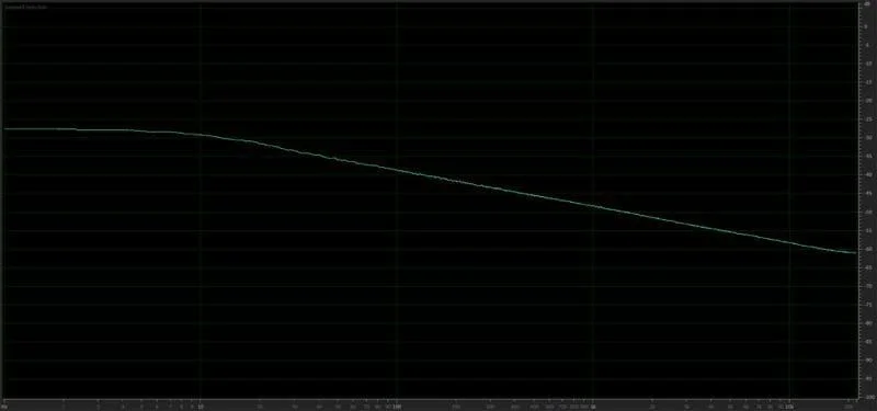
You can see that above 20 Hz, the level of the signal decreases at a rate of -10 dB per decade as frequency increases. This means that there is 10dB less signal energy at 1 kHz than at 100 Hz. When we relate this reduction in signal strength to power from our amplifiers, the ratio is also a factor of 10.
If we are playing pink noise through an audio system, and the amplifier sensitivity controls are set to produce 100 watts of power at 20 Hz, at 200Hz, the amp will be producing 10 watts. At 2 kHz, the amp will be producing 1 watt, and at 20 kHz, the amp delivers 0.1 watt of power to our speakers.
Power Density in Music
Another topic we should discuss before getting to speaker power ratings is how audio energy is distributed in the music we listen to. We looked at six audio tracks and analyzed their spectral content in Adobe Audition in the same way as the pink noise waveform above. The results are shown below:
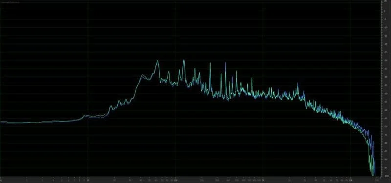
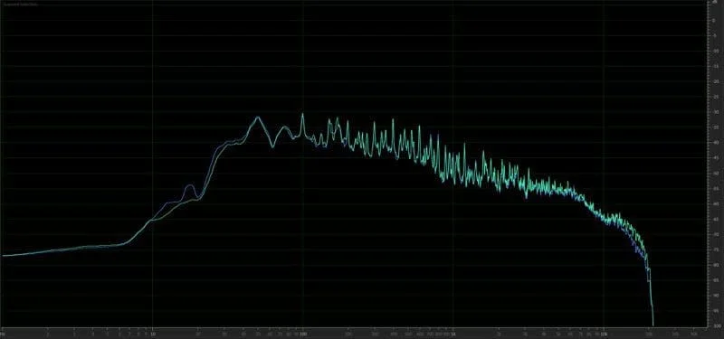
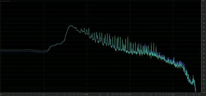
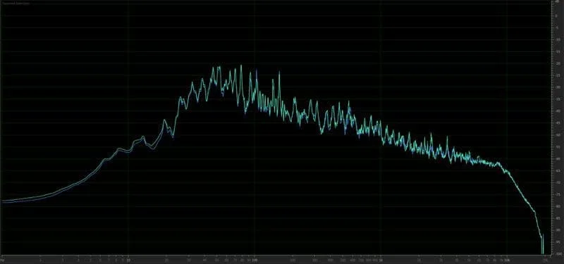
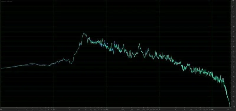
As you can see from this moderately diverse selection of music tracks, the audio energy is distributed similarly to our pink noise track. For this reason, many manufacturers use pink noise signals to test the power handling capabilities of their speakers.
How Speaker Power Handling is Tested
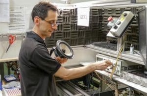 Depending on the brand, different companies use different processes to test the power handling capabilities of their speakers. It should be noted that some companies have detailed specifications for their testing procedures while others rely simply on data provided by their suppliers, and others guess based on the size of the voice coil used in the design. This is one of the key differences between companies that put significant effort into the design and development of their products and those that pick solutions from a catalog and have their name stamped on the basket and dust cap.
A properly engineered speaker testing process involves several steps. We’ll use a subwoofer for the first example. The technician performing the test would set the output of the amplifier using a sine wave audio track to represent a voltage level that equates to the power level they want to test. For a 4-ohm subwoofer that is to be tested at a power level of 200 watts, the sine wave voltage should be 28.28 volts rms or 40 volts peak-to-peak. Once this amplitude is set, pink noise that equates to an equal amplitude at 20 Hz is played to test the driver.
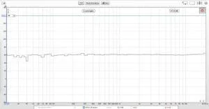
Once the levels are set and the speaker is mounted in the test fixture, this pink noise track is played at a continuous level until the speaker fails, or an adequate time has passed. Many companies use eight to 10 hours as a minimum test time and some extend this to 100 hours. After the temperature stabilizes in the speaker, the extended time test can help to confirm the suitability and reliability of chosen adhesives and materials used to build the speaker. In essence, it becomes a physical test as well as a power handling test.
Though it varies from brand to brand, in order for the speaker to pass the test, the Thiele/Small parameters of the driver must not have changed by more than a predetermined amount from those before the test began. A significant change in electromechanical properties indicates that something may have been damaged during the test and that too much heat was generated.
How Midrange and High-Frequency Speakers Are Tested
Because midrange drivers and tweeters can’t handle high excursion levels, they are tested in the same way as a woofer, but the test signal passes through a high-pass filter. Here’s an example:
Let’s say we want to test a 4-ohm tweeter, and we want to use the above standard to test it for 100 watts of power handling. That equates to a sine wave level of 20 volts rms or 28.28 volts peak-to-peak. The test begins with the amplifier calibrated to produce 20 Vrms using a sine wave while not connected to the speaker. Once the level has been set, pink noise is played through whatever high-pass filter the manufacturer specifies. For the purpose of this example, let’s say the filter is set at 2 kHz.
This is what the spectral analysis of the test signal will look like.
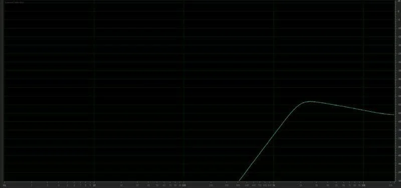
The average peak level of the test signal is now about 20 dB lower than it was at 20 Hz with a full-bandwidth signal. In terms of audio signal power, we have 1/100th as much power. Or 1 watt.
Are we saying that a tweeter rated to handle 100 watts of pink noise power, tested above 2 kHz, is only tested with 1 watt of power? Absolutely! That’s exactly how it works. Think about the physics of music. We want the audio produced by the tweeters to be balanced with that of the midrange drivers and the woofers or subwoofers.
In the real world, that tweeter can likely handle a lot more than just 1 watt of power. It may be able to handle 10 watts. Does this mean that it would be a good idea to rate the driver as being able to handle 1,000 watts of pink noise? Not likely. You know that someone who doesn’t understand how pink noise works is going to use a sine-wave track to set the gains on their tweeter amp and try and feed 63 volts (1,000 watts) into the tweeter. Of course, these same people will also call the speaker manufacturer and complain that the tweeter is “broken” and all they were doing was setting gain controls.
What’s the Point of Power Handling Specifications?
Speaker power handling ratings that use pink noise are based on criteria established for full-range home speakers. The tests mimic what the speakers would experience when listened to at high volume levels and are intended to indicate what amplifier power rating would be suitable to get the most from the speakers without damaging them. This specification doesn’t take into account what happens when an amplifier is driven into clipping – we’ll touch on that another time.
For now, the takeaway of all this is that setting up an audio system should start with setting the sensitivity controls on your subwoofer amp, then bring up the midrange and tweeter channel levels to create a balanced system. Odds are, you aren’t going to come anywhere close to maximum power from the mid and tweeter amps. Oh, and you don’t need a 150-watt amp to drive your tweeters.
