 Continuing from our brief introduction to the basics of car audio electrical theory and Ohm’s law, we are going to talk about electrical circuits and how to quantify the work done by that circuit. To keep the explanation simple, we’ll continue to look at DC circuits for now. The math involved in accurately calculating impedance and power in AC (alternating circuit) circuits can get quite complicated.
What Is an Electrical Circuit?
 Perhaps as important as the explanation of voltage, current and resistance is an explanation of the components required to make up a circuit. For a group of components to be considered a circuit, there needs to be a power source and a load, wired in a loop that allows current to flow. If you have a light bulb and you connect it to one end of a battery, it’s not a circuit until you connect the other side of the bulb to the other side of the power source.
The Concept of Electrical Polarity
 Another important part of our discussion about electricity is to understand the concept of polarity. Think of an AA battery that powers a pocket flashlight. One terminal will be positive with a + sign, and the opposite terminal will be negative with a – sign.
To add a little confusion to our world, there are two current flow descriptions in use. In what is called conventional current, it is said that current flows from the positive terminal to the negative. To keep you on your toes, the reality is that electrons flow from the negative terminal to the positive. All that matters for our discussion is that you know current flows from one terminal to another and in DC circuits, the flow is always in the same direction.
It’s Time to Do Some Work.

In physics, a statement about power describes the rate at which work is done over a period of time. More specifically, power is the amount of energy transferred from the power source to the load for a given unit of time. Work, thankfully, has no direction or polarity. You, a machine or a circuit is either doing work or it isn’t. The SI unit of power is the watt, so named after James Watt. One watt is equal to one joule of energy per second. A joule is one amp of current flowing through a load or 6.242×10^18 electrons over a period of one second.
To simplify, if we have 1 amp of current flowing in a circuit for 1 second, it is said that 1 watt of energy is transferred to the load.
Power Calculation Equations
 The simplest of all the equations to calculate power is Power = Voltage x Current or P = V x I. If we have one amp of current flowing through a load with a supply voltage of 1 volt, then 1 watt of energy is being transferred. In our cars, we typically talk about our 12V electrical system. If your battery is at 12V and you plug in a light that draws 1 amp of current, the light will receive 12 watts of power. Double the current, and you double the power.
Hold on tight; we are about to intertwine Ohm’s law with power calculations. In our example above, we know that for a light bulb to draw one amp of current from a 12V battery, the light bulb needs to have a resistance of 12 ohms. The equation to calculate resistance is R = V ÷ I, or in this case, 12 ÷ 1.
We can calculate the resistance of a circuit directly if we know how much power it is consuming and the supply voltage using the equation: Resistance = Voltage^2 ÷ Power. In our example, this would be 12^2/12, or 144/12, which is 12. Yay! Physics works!
Let’s Talk About Amplifier Power
 Let’s look at a more common example that you can use as a quick guideline in car audio applications. When looking at a new amplifier for your car, you know that many companies provide easy-to-understand and readily comparable specifications. Others like to play games so that they can print the biggest number possible on the gift box. If you look at an amplifier’s fuse rating, you can very quickly get an idea of how much power it can produce. If we have a compact four-channel amplifier that comes with a 30 amp fuse and we know our electrical system can maintain 13.2 volts, we can calculate the maximum power that we can feed into the amp. The equation is Power = Voltage x Current, or P = V x I. Substituting in our numbers, we have 13.2 volts and 30 amps for a product of 396 watts. If the amp has a 400-watt rating, then chances are the specifications are legitimate. If the amp has 800 watts emblazoned across the gift box, well, the physics doesn’t add up!
An Aside on Amplifier Power Calculations
 Without getting into specifics, most amplifier manufacturers use a supply voltage of 14.4 volts for amplifier power ratings. Using this value increases the maximum power we can feed into our four-channel amp to 432 watts. Keep in mind that amplifiers are not 100 percent efficient. A good Class D amp will have an efficiency of 80 percent to 90 percent. Assuming a worst-case scenario of 80 percent efficiency, the amp can produce about 345.6 watts.
If you want to forego the formal math, take the fuse rating of the amp and multiply it by 11 for a Class D amp or about 9 for a good Class AB amp. Depending on the manufacturer, these efficiency values will change dramatically. The idea is to get you into a ballpark and not to measure or predict the actual power production of the amp. If you see an amp with a 1,000-watt rating, it’s going to need about 90 amps of fusing on board.
Power and Ohm’s Law Calculations
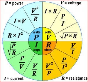 There is a very popular chart available that outlines all the Power and Ohm’s law equations available. If you know two values, you can easily calculate any of the other values using the equations found on the chart.
The next time you are out shopping for an amplifier or a set of driving or fog lights at your local mobile enhancement retailer, you can use the formulas we’ve provided to do some simple calculations to make sure you are getting a product that will perform the way you want. The staff at the store is available to answer any specific questions you may have. In the next car audio electrical theory article, we are going to talk about wiring loads in series and parallel.
