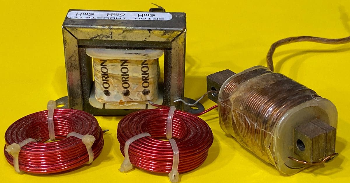
Back in the late ’80s and early ’90s, having an amplifier or a radio with a built-in high- or low-pass crossover was rare. To filter the audio signals going to our speakers, installers and technicians would use inductors and capacitors on the speaker wires. We recently took a look at how capacitors work, so let’s dive into inductors to understand their function and application in audio systems.
What Is an Inductor?
Inductors are often referred to as coils and chokes. They are an elegantly simple device, and unlike capacitors, they’re something you can create or modify at home without needing fancy production equipment. In most cases, an inductor is simply a tightly wound coil of wire. Some inductors are donut-shaped, while others are wrapped around an iron core. If you’re into electronics, you’ll see that some of the iron-core units look similar to a transformer.
An inductor is the second of the three most fundamental passive electronic components, alongside resistors and capacitors. Without getting painfully technical, we know that a magnetic field is created around the conductor any time current flows in a conductor. The wire in an inductor is wrapped in a coil to intensify the magnetic field. Once the magnetic field is established, it doesn’t like to change in amplitude, and as such, neither does the flow of current. When the supply voltage is removed, the magnetic field will collapse and produce a current in the polarity opposite to what created the magnetic field. In layman’s terms, you can think of an inductor as a way of storing current flow momentum.
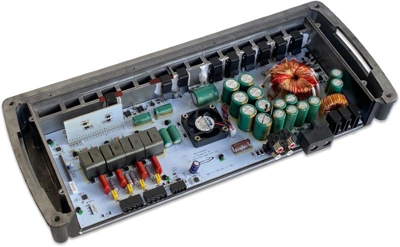
Inductors make great high-frequency noise filters in direct current (DC) circuits, considering their characteristics. If you have a power source and a constant load, adding an inductor can filter out voltage ripples and noise from the supply. If the current required by the load varies, the inductor may oppose these requested variances. Many car audio amplifiers will use a small inductor in series with the positive battery input terminal to filter high-frequency noise from vehicle charging systems.
Inductors are rated in units called henries, abbreviated with a capital H. We’d need to define a bunch of other terms like weber, flux density and volt-second to thoroughly explain what a henry is. We’ll leave that to the college and university professors for now.
Calculating Inductive Reactance
We need to look at an inductor from the perspective of the alternating current (AC) signal from an amplifier. Low-frequency (bass) audio signals change amplitude and current direction slowly compared with high-frequency information.
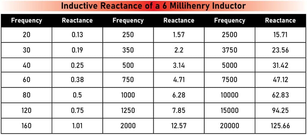
Just as we described with capacitors, inductors present opposition to AC current flow that increases with frequency. The formula to calculate capacitive inductance is Xl = 2 x Pi x f x L, where f is the frequency and L is the inductance in henries. Let’s use an example of 100 Hz and an inductor rated at 6 millihenries (0.006 henry). Plugging those values into the equation gives us an inductive reactance of 3.77 ohms. Once again, you can’t measure this opposition to AC current flow with an ohmmeter, as it uses DC current. You can, however, measure the AC voltage drop across an inductor with a voltmeter. If you know the current through the inductor, you can calculate its impedance at that frequency. If you need to fine-tune the value of an inductor for a specific application, you can remove windings to reduce the inductance. With that said, designing complex passive crossover networks is well beyond the scope of this article.
As you can see from the chart above, the inductor opposes AC current flow more as frequency increases. When we wire an inductor in series with a speaker, the amplifier’s output voltage is divided between the inductor’s capacitive reactance and the speaker’s resistance. We can calculate the voltage across the speaker (Vs) using a simple voltage divider network formula where Vs = Vamp x (Rs/(Rs + Xl). In this formula, Vamp is the output voltage of the amplifier, Rs is the speaker’s resistance (we will ignore the speaker’s impedance curve for now), and Xl is the inductive reactance of the inductor. If we use an example of an amplifier producing 5 volts (which is 6.25 watts), the chart below shows us how much power the speaker will receive at different frequencies.
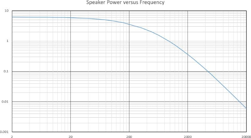
From the chart above, it’s easy to see that high-frequency energy going to the speaker is reduced with the inductor in the circuit. We call the network of a speaker (or subwoofer) wired in series with an inductor a first-order low-pass filter network. As a result, the signal attenuates at a rate of 6 decibels per octave.
Important Inductor Formulae
There are a few things we need to know to work with inductors. First, they’re used as a low-pass filter on subwoofers where we want a woofer or midrange speaker to start playing or on a midrange speaker where we wish a tweeter to take over. As mentioned, we wire the inductor in series with the load.
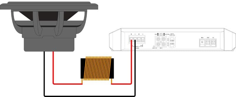
Suppose we want to choose the value of an inductor needed for a specific crossover frequency. In that case, we can rearrange the inductive reactance calculation so that Xl equals the speaker’s resistance at the frequency we want. This value of 4 ohms means that power is split between the speaker and the load, resulting in the -3 dB frequency of the circuit. For our example, while ignoring the reactive properties of loudspeakers, we want Xl to be 4 ohms. To calculate the inductance, the formula is L = Xl/ (2 x pi x f). If we want a low-pass filter at 100 Hz with a 4-ohm subwoofer, we need a 6.37-millihenry inductor.
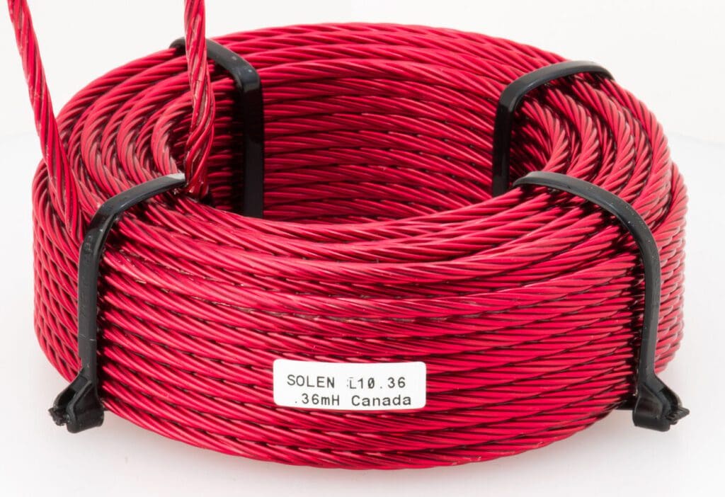
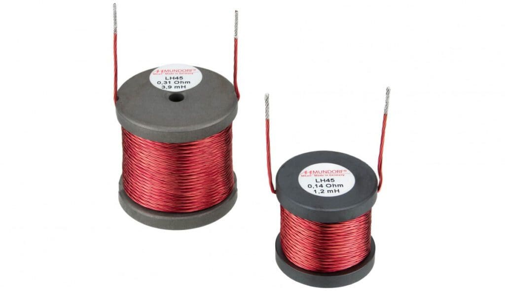
As with anything in the automotive audio industry, there are good components and great ones. A coil of wire around a nail is an inductor. Companies such as Solen and Mundorf manufacture premium inductors that offer better performance, including less capacitance and little to no unwanted resonances. Yes, a detailed analysis of an inductor will show that it has small amounts of resistance and capacitance along with a large amount of inductance. As is always the case, nothing is purely what it seems, and when designing complex multi-component crossover networks, these additional considerations need to be taken into consideration. If you’re looking for a coil to use on a sub because you don’t have an active crossover, that’s totally different.
Capacitors, resistors and inductors are used in complex configurations to attenuate the output of speakers at higher rates than just 6 decibels per octave. For these networks to function as intended, the designers need to consider that speakers are not resistors but have a resonant impedance peak and inductance of their own. The crossover network component values need to be adjusted for these reactances.
Applications for Inductors in Car Audio Systems
These days, amplifiers and source units typically include both low- and high-pass crossovers. As such, building crossover networks using passive components is less common. With that said, knowing how these components work is important to understanding car audio system design, especially when a component speaker set is used. Drop into your local specialty mobile enhancement retailer today to audition a set of component speakers for your vehicle.
