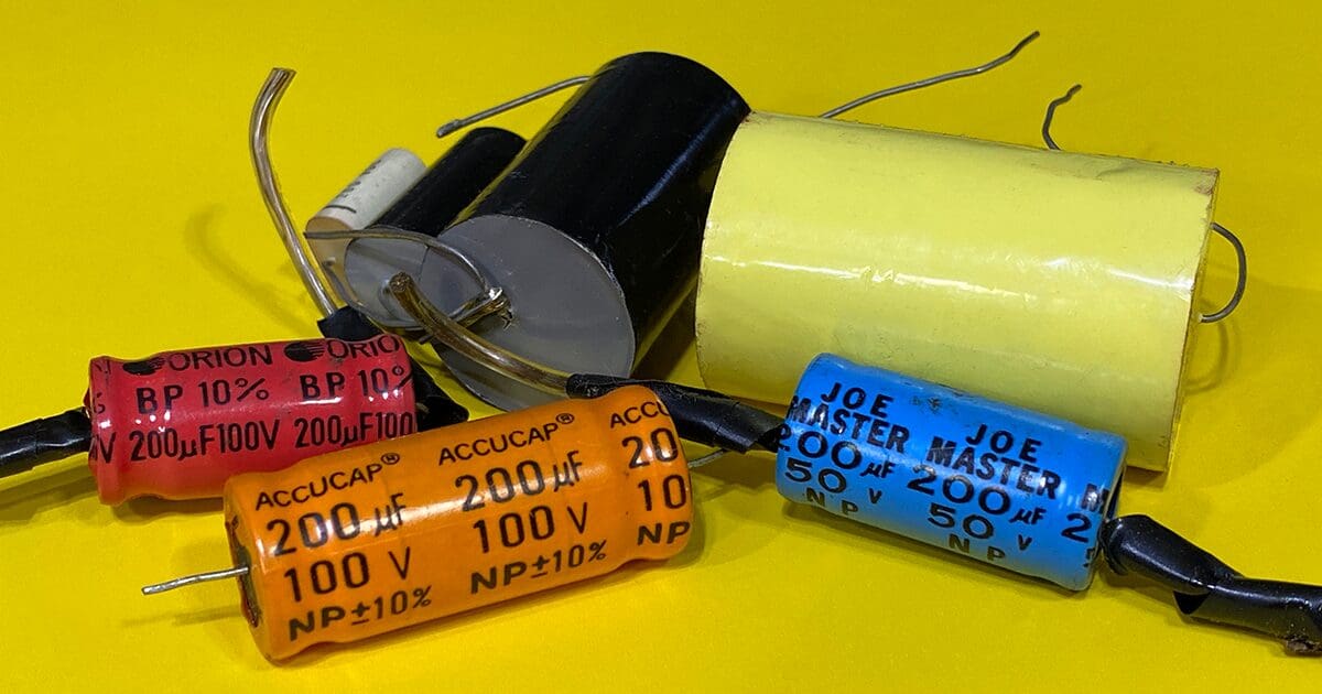
For decades, car audio installers have used capacitors to reduce the bass that small speakers would reproduce. I vividly remember installing 47-microfarad capacitors inline with a set of 3.5-inch speakers in the dashes of Fox-body Mustangs back in the ’80s and ’90s. Passive crossover components like these are still an essential part of the car audio industry, even with the proliferation of digital signal processors and amps with adjustable active filters. So, let’s take a look at how capacitors work to block bass signals.
What Is a Capacitor?
Capacitors are passive electronic components that store energy in the form of an electric field. If you were to take a capacitor apart, you’d find two metal plates (or sheets) that are separated by paper or tissue soaked in a dielectric. A fourth non-conductive isolation layer will allow the assembly to be rolled up like Christmas wrapping paper without allowing any of the conductive components to short out. If you were to apply a voltage to the terminals, an electrical charge would build up across the plates. Once the voltage across the terminals matches the supply voltage, there is no current flow into the capacitor.
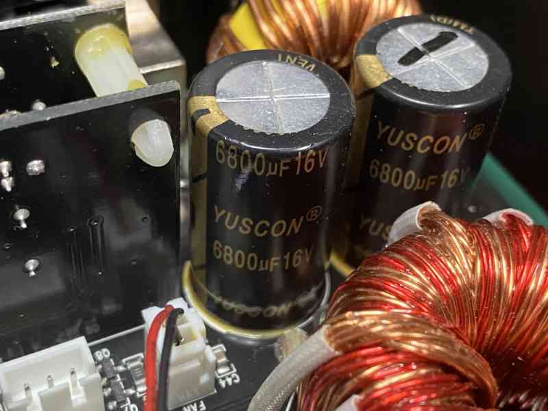
From a fundamental electrical standpoint, capacitors oppose changes in voltage. This characteristic makes them ideal for use as energy storage and noise filtering devices in amplifiers. If there are tiny voltage ripples (noise) in the power feed to the amp, the capacitors filter them out by absorbing and releasing energy to fill in the peaks and valleys. For example, suppose you crank up the volume on your radio, and the amplifier suddenly needs a lot of current and voltage to drive the speakers. In that case, the capacitors in the power supply section of the amp will attempt to maintain all the internal power supply voltages to keep things running smoothly.
Capacitors in Alternating Current Circuits
The last few statements in the previous paragraph describe how capacitors work in direct current (DC) circuits. When it comes to alternating current (AC) audio signals, capacitors act quite differently. How quickly capacitors charge and discharge depends on their size or value. Capacitor storage is specified with two numbers: voltage and capacitance. Capacitance, specified in farads, is the SI unit for electrical charge storage. Most of the capacitors used in electronics and audio systems are relatively small, and as such, we use the unit microfarad, which is 1/100,000 of a farad. You’ll often see this written as uF, but to be correct, the letter “u” should be replaced with the Greek letter mu, which looks like a lower case “u” but with a slightly curved tail on the right and a long tail on the left.
Capacitors can act as resistors to AC signals, even though they don’t (theoretically) dissipate any heat. If you use an ohmmeter, you won’t be able to measure the resistance across the terminals, though – it’s not resistance. The opposition to AC current flow is called capacitive reactance, and it varies with capacitor size and frequency. The formula to calculate capacitive reactive (which has the value Xc) is 1/(2 x pi x f x C), where f is the frequency and C is capacitance in farads.
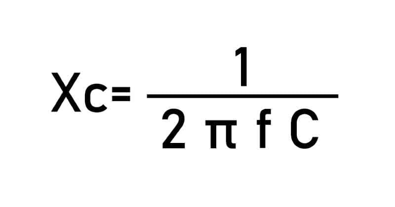
Let’s do an example calculation with a 100-microfarad capacitor. If we want to know what opposition it presents to an AC signal with a frequency of 150 hertz, then we work out 1/(2 x 3.1416 x 0.0001 x 15), which is 10.61 ohms. If we double the frequency to 300 hertz, the reactance drops to 5.3 ohms.
Wiring Capacitors as Bass Blockers with Speakers
If you want to wire a capacitor to a speaker such that it works to reduce the bass information a speaker sees, it must be wired in series with the speaker. Wired this way, it forms a voltage divider with the A/C signals coming from the amplifier.

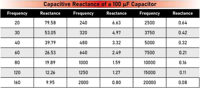
Let’s look at our 100-microfarad capacitor and its behavior at different frequencies.
The capacitive reactance chart shows that the capacitor presents less opposition to current flow as frequency increases. However, the reactance becomes infinite if we continue the graph to lower and lower frequencies. We can describe capacitors as blocking the flow of direct current.
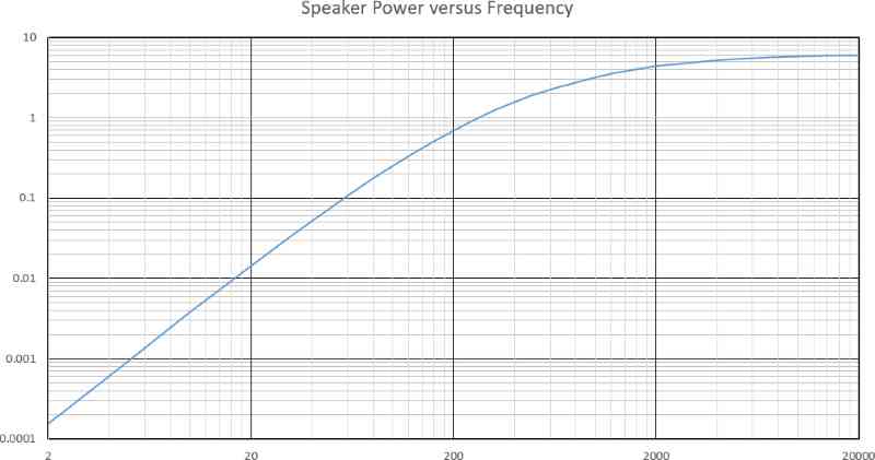
There are a few things to keep in mind as we move to the next step in this explanation. We typically use charts with a logarithmic scale when we look at audio frequencies. In those charts, 100 hertz is as far from 1,000 Hz as 1,000 from 10,000. Second, power to a speaker is the square of the voltage. As such, the vertical scale is also viewed in the logarithmic domain.
The speaker (or load) and the capacitor are wired in series. Any voltage produced by the amplifier will be divided between the capacitor and the speaker. The formula to calculate the voltage across the speaker is Vamp x (Rs / Rs + Xc), where Vamp is the voltage out of the amplifier, Rs is the speaker’s impedance, and Xc is the capacitive reactance of the capacitor. The graph below shows the power across the speaker at different frequencies based on this voltage divider calculation.
If we analyze the data carefully, we can see that the power across the speaker decreases at a rate of about 6 decibels per octave. We refer to this as a “-6 dB/octave high-pass filter” as it allows high-frequency information to pass to the speaker. You may also hear this called a “first-order high-pass filter.”
One More Important Piece of Math
When choosing a value for a capacitor, it’s typically done based on where we want the speaker’s output to be down 3 decibels from its nominal value. We call this the crossover frequency. We can rearrange the capacitive reactance formula to provide a capacitor value for a given frequency by swapping the location of Xc and C and making Xc equal to the speaker’s impedance. We can also calculate the crossover frequency of a known-value capacitor and speaker by swapping Xc and f. For our example, our crossover frequency is 397.89 hertz.
Where Are High-Pass Filters Used?
As mentioned at the beginning of the article, capacitors are wired in series with speakers to reduce low-frequency information that reaches the speakers. This effect reduces the speaker’s excursion requirements and reduces the amount of power sent to a speaker. Years ago, many audio systems were constructed with a single two-channel amp and large networks of capacitors and inductors to divide the audio signals between subwoofers, midrange drivers and tweeters. Today, many of the tweeters in coaxial speakers and some of the less-expensive component speaker sets are protected by a single inline capacitor. Capacitors are also very useful as a protection device in active systems when set a few octaves below the electronic crossover point. Should something “go wrong” with the settings, the capacitor can usually prevent a tweeter from being damaged.
One last note about capacitors. If you’re shopping for a cap or, as they are sometimes called, a bass-blocker for a speaker, make sure the device is designed for AC signals. Electrolytic capacitors used in amplifiers and “stiffening” devices are polarized as charging systems. They’ll swell up and explode if you feed them a high-voltage AC signal or wire them backward. You’ll need to make sure you are using non-polarized capacitors for filter networks.
If you need a hand picking the right capacitor for a speaker in your car, drop by your local specialty mobile enhancement retailer. They often have capacitors in stock or can pillage parts from a passive network included with a speaker set that wasn’t used.
