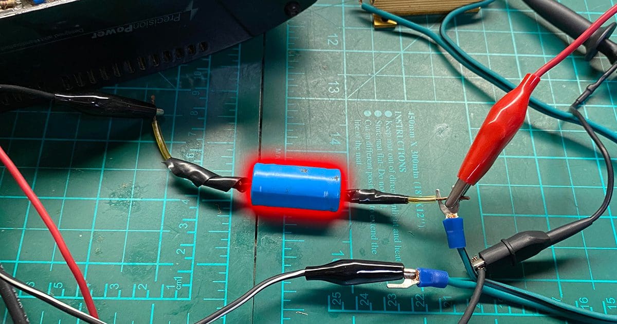
A few months back, I wrote a very detailed article that explained what happens when you push the output of an amplifier (or source unit) to the point that the signal clips. To be clear, and much to the dismay of many who think otherwise, there is NO DC component riding on the top of the waveform. What you see there is a large number of harmonics that produce the top of what is effectively a square wave. It was no surprise that my explanation would be challenged, as this defies what many in the industry believe to be fact. I love a good challenge, so here’s the proof you’ve asked for.
Step 1 – Understanding AC and DC Signals
This explanation will require a prerequisite understanding of some basic electrical and electronic concepts. First, let’s start with an explanation of the difference between an AC and a DC audio signal. In a DC signal, the current travels in only one direction. If you put an AA battery in a flashlight and turn it on, current flows steadily from the battery, through the bulb (or these days, an LED) and back to the other battery terminal. This is Direct Current flow, or DC for short.

If you connect a voltmeter to a power outlet in your home or office and it’s set to measure DC voltage, you’ll measure little, if any, voltage. If you switch the meter to the Alternating Current (AC) range, you should measure around 118 to 120 volts RMS. The voltage fed into our homes cycles back and forth between positive and negative 60 times a second and has a roughly sinusoidal shape. This power delivery method, initially proposed in the 1880s as transformers, could be used to step voltages up and down to reduce losses in long-distance power distribution networks. If we check the dictionary for a definition of Alternating Current, we find “a continuous electric current that periodically reverses direction, usually sinusoidally.”
Audio signals from a radio or amplifier are AC in nature because their amplitude and frequency content represent pressure measurements from a microphone. Low-frequency signals change direction very slowly, whereas high-frequency signals change pretty quickly. Audio signals from an amplifier are fed to a speaker to move the cone forward and rearward. The changing polarity of the current causes this inward and outward motion.
Part 2 – Understanding Capacitors
A short while back, I wrote about how capacitors can be used as filters to limit how much low-frequency audio information reaches a speaker. When a capacitor is wired in series with a speaker, it forms a voltage divider with that speaker. The formula to calculate the reactance of a capacitor is Xc = 1 ÷ (2 x Pi x F x C), where Xc is the capacitive reactance, F is frequency, C is capacitance in henries and Pi is 3.14159. At very low frequencies, say 20 Hz, a 200-microfarad capacitor will have a reactance of just under 40 ohms. At 5 hertz, the reactance is 159 ohms, and at 1 Hz, 795 ohms. As frequency decreases, reactance increases, so less current flows, and less power is delivered to the speaker.
If you try to measure the impedance of a capacitor when a DC signal is applied, which has a frequency of 0, you get infinity. From a math standpoint, you can’t calculate the value because you’re attempting to divide by 0. In short, capacitors don’t pass DC.
Part 3 – Clipped Audio Signals
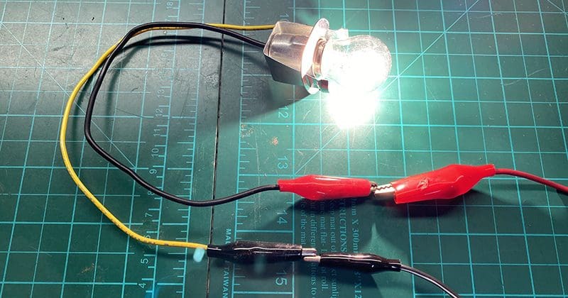
Let’s wire up a small circuit to demonstrate this. I connected a 12-volt lamp to my test bench’s 14-volt DC power supplies. Unsurprisingly, the lamp lights up.
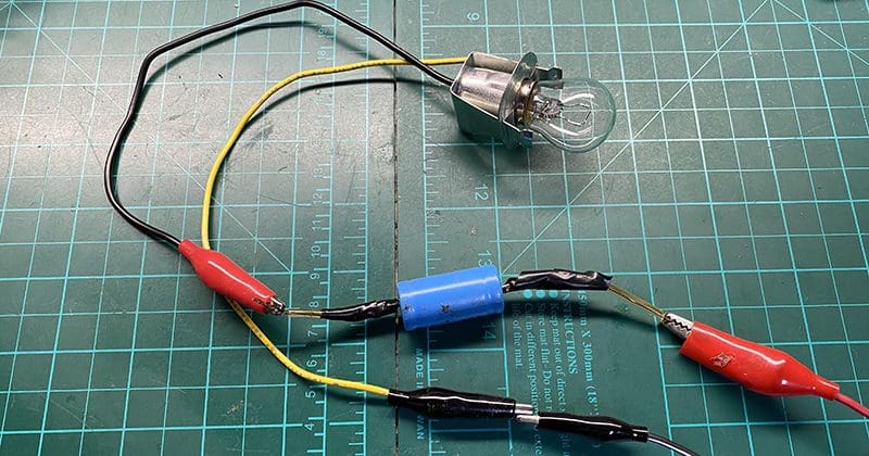
Now, I’ll add a capacitor in series with the lamp. The lamp doesn’t illuminate. This is because capacitors don’t pass DC.
Let’s look at the output of an amplifier that has been driven to the point that the top and bottom of the output signal are clipping.
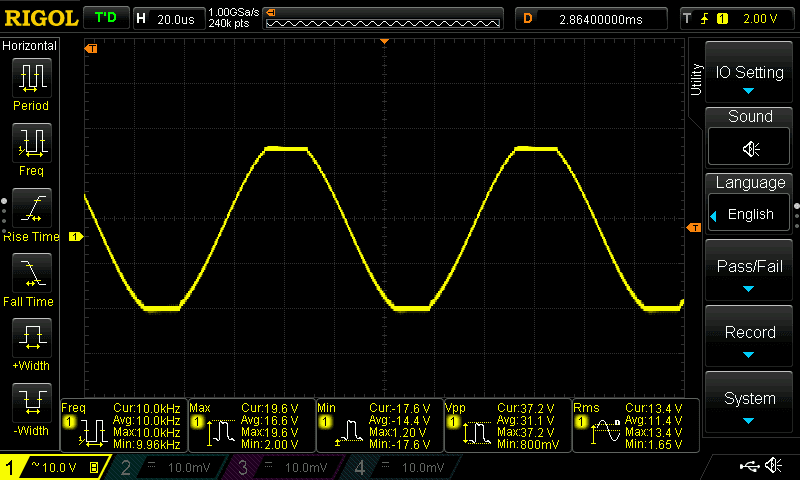
As we can see, this is an AC signal as the voltage swings from positive to negative continuously. The flat parts of the waveform are caused by the amplifier not having high enough rail voltages or not enough current delivery capability to follow the shape of the input waveform. These are where people mistakenly believe that there is DC content in the waveform.
Let’s do a little test that combines what we’ve reviewed in this article. If we know that capacitors block DC signals but pass AC signals, what might happen if we wire a capacitor in series with a speaker when the amplifier is clipping? If the flat portions of the waveform are DC, then the capacitor will block them. If they are a collection of high-frequency harmonics, then the cap should not affect that information passing to the speaker.
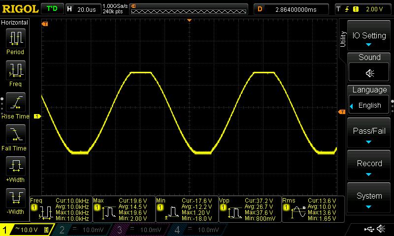
As you can see, there is almost no change in the waveform. The flat portions at the top and bottom are still flat. Why? Because that’s not DC, it’s a combination of harmonics that produce what appears to be a momentarily constant waveform in amplitude.
Let’s look at this another way. Here’s the spectral analysis (frequency response) of the 10-kHz clipped waveform with no capacitor in the signal path.
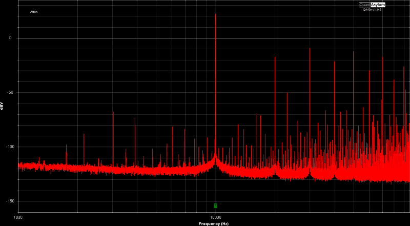
As you can see, we have high-level harmonics at 20, 30, 40, 50, 60, 70, 80 and 90 kHz. These unwanted high-level harmonics create the waveform’s small, seemingly flat portions.
Now, let’s add the cap back into the circuit to see if it affects the frequency content.
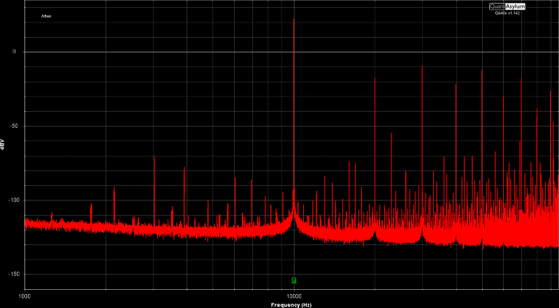
It’s pretty clear to see that there’s effectively no change in the frequency content or amplitude of the waveform when we have the cap in the circuit. Why? Because capacitors pass high-frequency AC information.
To summarize, the flat portions at the top and bottom of a clipped AC waveform are NOT DC. They are a combination of harmonics that produce a momentary consistent voltage when viewed in the time domain. When viewed in the frequency domain, we can see the presence of these harmonics, which were not in the original audio signal.
Why does clipping matter? Aside from sounding terrible, it dramatically increases the amount of power being sent to the speaker. This extra power generates more heat. The excess heat can damage the voice coil. Because the extra power is contained in higher frequencies, tweeters often suffer the brunt of the abuse.
How can you avoid all these complications? Choose a high-quality amplifier that has enough power to drive your speakers to the volume level you want. More importantly, make sure the specialty mobile enhancement retailer you’re working with has a repeatable procedure for setting the level controls on your amplifiers. It should take into consideration any equalization applied by the source unit or a digital signal processor and crossovers.
