Some of the most common car audio questions on social media are about finding a good ground location for an amplifier. Thinking about the topic, using the term ground to describe the negative power connection to the amplifier might imply it’s not as important as the positive battery connection. Both connections must be equally capable of passing all the current the amplifier needs. Neither is any less important than the other. Let’s discuss good amplifier grounding locations and how modern vehicle construction changes the rules.
What Is an Amplifier Ground?
For any electric or electronic device to operate, current must pass through it. Think of a simple halogen car headlight or turn signal bulb. If you connect one terminal on the bulb to the battery’s positive post, it won’t illuminate. You need a complete path for the current to flow. So, you need a connection from the other bulb terminal to the negative battery post. Both conductors will have the same amount of current passing through them. This second statement is critical to car audio amplifier installations.
Maximizing Power Delivery to Car Audio Amplifiers
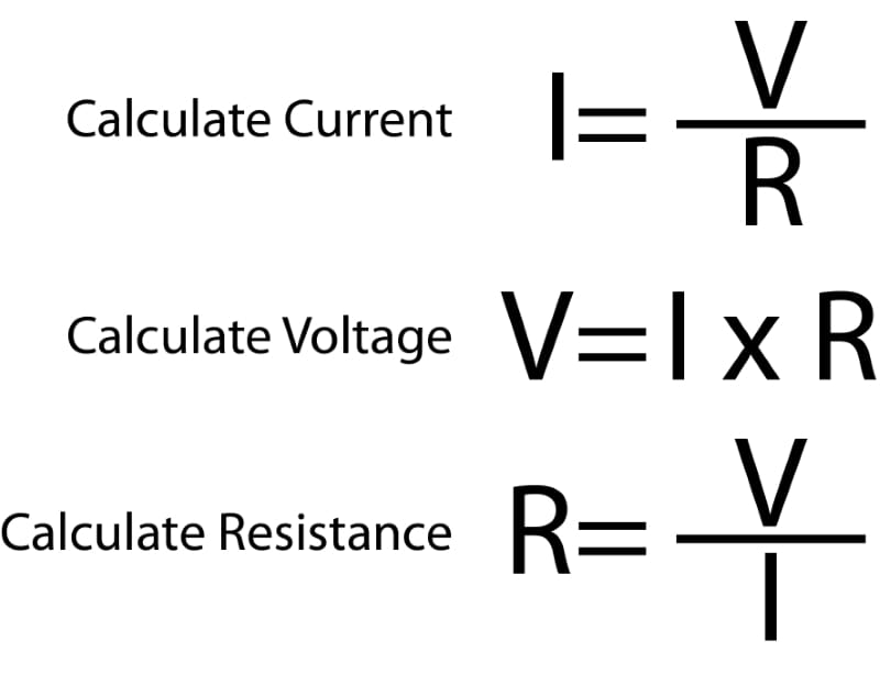
Let’s talk about Ohm’s law for a second. Though we could write a book on the topic and its importance to car audio systems, we’ll try to keep things focused on getting power to an amplifier. Ohm’s law states that when 1 amp of current flows through a resistance of 1 ohm, 1 volt will be present across that resistance. If we double the current to 2 amps, we get 2 volts across the 1-ohm resistance. We can change any numbers we want, but their relationship remains the same. More current means more voltage drop. Increased resistance means more voltage drop. Additional voltage means more current. They are all intertwined.

Let’s put the above statement into practice. Because there is resistance in the cables and connections between your amplifier and the power source (battery and alternator), a voltage will present across that resistance as current flows through the conductor. By way of an example, 4 AWG, all-copper, full AWG-spec power cable with a length of 17 feet should have a resistance of 4.56 milliohms or less and no more than 4.8 milliohms to be compliant with the ANSI/CTA-2015 Mobile Electronics Cabling Standard. That doesn’t seem like much resistance. It’s not and doesn’t affect amplifier performance significantly until we start drawing significant amounts of current.
Let’s say we have a good quality amplifier that can produce 100 watts of power by drawing 10 amps of current at 14 volts. Ten amps of current results in 45.6 millivolts being present across the length of the positive power cable. However, that power cable is only one part of the power delivery system. We also need a ground return path. What is the path’s resistance between the amplifier’s negative terminal, the battery’s negative terminal, and the alternator’s chassis? For the sake of this example, let’s assume it’s equivalent to a piece of 4 AWG wire. If so, we’d lose another 45.6 millivolts across this connection. Let’s round our losses to 100 millivolts or 0.1 volt.
More Power, More Power Loss
What if we turn the volume up a few notches, and the amp wants to draw 50 amps of current and produce roughly 500 watts of power? First, that’s only an increase in output of about 7 dB SPL, assuming the subwoofer can operate linearly with the increased power. Second, each voltage drop has now increased to 228 millivolts. Let’s call it 0.5 volt total. Our assumptions don’t include any losses at connections, crimp terminals or fuses. We are wasting 3.5% of the voltage from the charging system in cable losses. Those losses represent about 23 watts of heat.
Many will say that 4 AWG wire has a maximum power delivery capacity of 80 or 100 amps, depending on who you talk to. Eighty amps of current would result in 0.73 volt dropped across the pair of cables, and 100 amps results in a 0.91-volt drop. The latter is 6.5% of the voltage from the battery, meaning your amp only sees 13.09 volts, reducing the maximum power it can produce. If you listen to music and not test tones, 100-amp bursts are likely a safe limit.
Modern Vehicle Assembly Methods
The math outlined above assumes that the vehicle chassis has the same current carrying capacity as a piece of 4 AWG power wire. Most unibody vehicles built between the ’80s and roughly 2010 might be capable of passing this much current through the chassis. However, things have changed in recent years. Automobile manufacturers constantly look for ways to simplify production, make vehicles more rigid, improve safety and reduce costs.
According to Collision Repair Magazine, the 2018 Hyundai Accent uses 323.2 feet (98.5 meters) of structural adhesive to assemble the chassis. As a benefit to the automobile manufacturer, adhesives provide a continuous bond between metal panels to disperse loads more evenly. Adhesives eliminate the need for weld spatter cleanup. Adhesives can bond panels together that aren’t accessible for spot welding. On the downside, adhesives don’t conduct electricity.

Each panel has a solid path for electricity to flow to the next in a unibody vehicle chassis assembled using spot welds. Sure, there might only be a few square inches of weld, but it’s better than a bead of non-conducting adhesive that insulates each panel from the next. The adhesive might help prevent corrosion but also eliminates the chassis as a good ground return path for high-current accessories like car audio amplifiers.
New Vehicles Use More Structural Adhesives
In February 2022, Polestar, the Swedish automotive brand that produces electric vehicles, announced that the forthcoming Polestar 5 would have a chassis constructed of bonded aluminum sections.

What about an even more exotic vehicle? Hypercars like the Koenigsegg Regera use a one-piece carbon fiber monocoque chassis. Yes, carbon fiber is conductive. No, it can’t pass enough current to serve as a ground point for an aftermarket amplifier. I don’t know many installers brave or daring enough to drill a hole in a multimillion-dollar carbon fiber chassis to ground an amp.

What’s a Good Ground Location for My Amplifier?
Let’s get back to the original question, shall we? Where on the chassis of a unibody vehicle is a good ground location? Based on many variables, we aren’t 100% sure there’s a universally good location. Drilling a hole through the floor or trunk panel and bolting a ground cable to it might work. However, you don’t know if you are losing a lot of voltage unless you try it. We wrote a great article about measuring the performance of cables to check ground return paths. To know whether you’re in good shape, the measured voltage drop should be less than 50 millivolts per 100 watts of power. So if you have a 1,000-watt amplifier, an acceptable voltage drop might be 500 millivolts. If you measure more voltage, then you should upgrade the wiring.
How do I upgrade the wiring? If the installer has measured a significant voltage drop across the power cable to the battery, you need a second cable or a larger cable. If the voltage drop is across the ground connection, have the shop installing your audio system run a ground directly to the alternator case and battery. We would connect the wire to the alternator case, as it provides a higher voltage than the battery during normal operation. A secondary large-gauge cable can run from that ground on the alternator to the battery.
The dedicated ground wire should connect to a ground point near the amplifier. Using this method, the amplifier can use the upgraded wire and the chassis to pass current, resulting in less resistance and, subsequently, less voltage drop. Credit to the engineers at JL Audio for this suggestion several decades ago. They call this the parallel ground.
Overcurrent Protection Devices
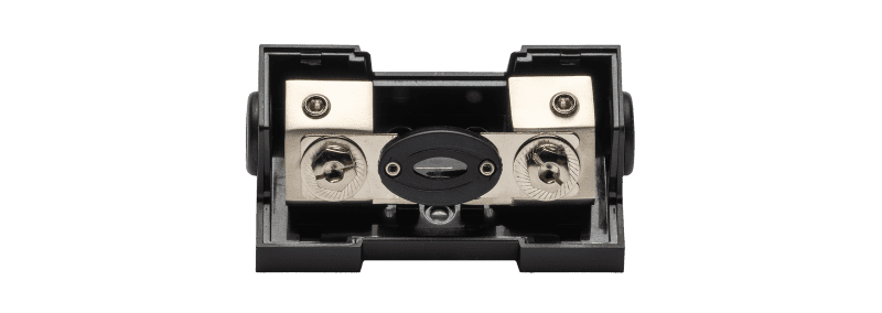
Another upgrade you can make is to switch from an ATC or AGU fuse or circuit breaker to an ANL fuse holder. Our testing shows circuit breakers waste more power than a good, fused connection where the fuse bolts in place.

If you want to avoid the cost of having the shop working on your vehicle measure ground locations, then have them run a second wire for a ground right from the beginning. It should only take a few extra minutes to run, and two ring terminals will ensure that the connection is secure at both ends. The results are guaranteed to be beneficial. Your amplifier will appreciate seeing more voltage and will be able to produce more power. Chances are, it will also run cooler and subsequently last longer.
