The BestCarAudio.com team received a great question about subwoofer polarity and how a crossover affected the phase at the crossover point. Specifically, the question focused on whether the subwoofer polarity needed to be reversed if the sub amp used a -12 dB/octave filter. The short answer is yes. As always happens with audio systems, the full answer isn’t as simple once we consider the vehicle and function of the speakers. The only suitable solution is to test the system once it’s integrated into the car. Let’s explain why.
The Importance of Audio Signal Phase
If you aren’t familiar with the concept of phase in audio signals, you should read this article first. In short, phase describes the timing relationship between two signals. If we consider a sine wave as our reference waveform, two signals where the voltages rise and fall simultaneously are in phase. Suppose one waveform moves upward while the other moves downward; one of those signals has the opposite or inverted polarity. They are not necessarily 180 degrees out of phase with each other. If that last sentence didn’t make sense, please read that article. It’s a matter of semantics, but it’s essential to completely understanding the concept.
Phase comes into play in two scenarios in car audio systems. The relationship between the left and right channels needs to be in phase. Likewise, the audio signals at the crossover points between two drivers must also be in phase. The latter is what we will focus on in this article.
We need the output of both signals to sum at these frequencies for the system to produce a flat frequency response. If the polarity of one signal is inverted relative to the other, we will get a sharp dip in the frequency response at the crossover frequency.
Crossovers Affect Phase
Things get complicated in a discussion about crossovers because 99% of the filters used in car audio systems affect the signal phase at the crossover point. We’ll look to the ARC Audio ARC DNA software and its Plot feature to help explain this.
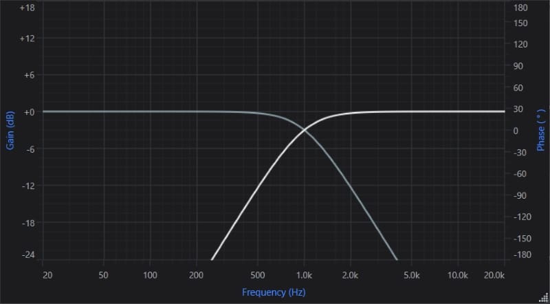
The graph below shows a high-pass and low-pass crossover set to 1 kHz with a second-order -12 dB/octave Butterworth alignment. These results are similar to the crossovers built into the typical car audio amplifier.
Where things get somewhat complicated is when we take signal phase into account. Until now, we’ve described phase as a relationship between two waveforms. We’ll add a bit of complexity to that discussion by talking about the signal phase at the crossover point relative to a signal with no crossover. As you may have predicted, something happens to phase when we apply crossovers.
The graph below shows the same response curves but adds phase response curves for each signal.
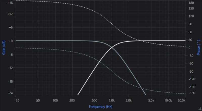
Let’s start with the gray low-pass crossover phase trace represented by the dotted gray line. At frequencies well below the crossover point, the signal phase trace follows the 0-degree line in the middle of the graph. The phase then shifts to -180 degrees by the top of the chart. What’s crucial to this discussion is that the phase is at -90 degrees exactly at the 1-kHz crossover point.
Now, let’s look at the dotted white high-pass filter trace. At low frequencies, the phase of that signal has shifted 180 degrees positive relative to the audio content well above the crossover point. Just as with the low-pass filter, we need to consider the phase at the crossover point. In this case, we see that it’s at +90 degrees.
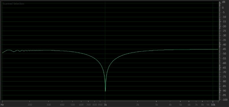
Think back to what we said a few paragraphs ago. At the crossover point, we need the signals to be in phase so we don’t get a dip in the response at the crossover point. If the woofer, which is fed by the low-pass filter, is at -90 degrees phase at the crossover point, and the tweeter fed by the high-pass filter is at +90 degrees at the crossover point, the two signals will effectively cancel each other out. Why? The phase relationship between -90 and +90 is 180 degrees. One driver will be moving forward while the other will be moving rearward. The result will be a massive dip in the frequency response at the crossover frequency, and our audio system won’t sound very good. We used Adobe Audition to simulate the results below.
Here are a few side notes about this discussion. The charts above work the same for a woofer and subwoofer filtered around 80 hertz. We used 1-kHz crossovers so the information is easier to see on the frequency response plot.
So what’s the solution to getting the signals to sum properly at the crossover point if using filters causes a 180-degree phase shift between them? The solution is simple: We reverse the polarity of one of the signals. Rather than one speaker moving rearward while the other moves forward, we reverse one speaker so they both move in the same direction. In most car audio systems, it’s easiest to reverse the polarity of the subwoofers. The polarity can be reversed by swapping the positive and negative speaker wires. Some amplifiers include a polarity switch that has the same effect as reversing the speaker wires.

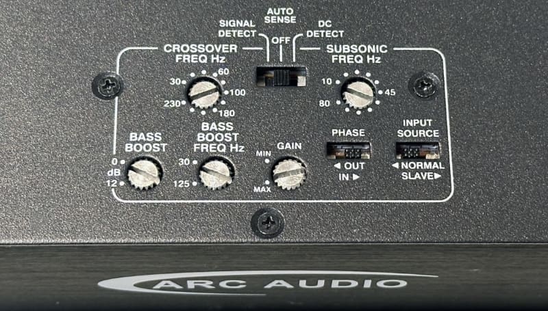
The audio signals will sum together constructively when the speakers move in the same direction at the crossover frequency. With both filters set to the same frequency using second-order Butterworth filters, we run into a different problem in that the result is a bump of 3 dB. We’ll talk about that another time.
Reversing Subwoofer Polarity Can Help Improve Audio System Performance
Here’s one last thought on the question about speaker polarity at the crossover point. The absolute answer to whether speaker polarity needs to be inverted depends on which way the subwoofers are facing. The original question asked whether the polarity of the subwoofers should be reversed. From the standpoint of the phase effect of the crossover, the answer is yes: The subwoofer polarity should be reversed.
If the subwoofers are in an enclosure in the back of the vehicle, and the drivers are facing toward the cab’s interior, chances are our answer stays the same, and the signal going to them needs to be reversed. What if the subwoofer enclosure is facing rearward into the cargo area? Does the signal still need to be changed? What if the subwoofers are mounted in the enclosure so the baskets are visible and the cones point into the enclosure? What if the amplifier has a different crossover slope or alignment? Does the phase relationship change if the front speakers are in the dash instead of the doors? What if the front speakers are in the kick panels? There are three ways to get answers to these questions.
If you have a good ear, you can listen to the system and have your installer reverse the polarity of the subwoofers. Choose whichever setting produces the best midbass output.
A simple and accurate way to know whether the phase relationship between the woofers and subwoofer is correct is to use a real-time analyzer to measure the frequency response in the vehicle. Your installer can reverse the polarity of the subwoofer and look at the RTA graph to see which option produces the smoothest response around the crossover point. The differences should be noticeable.
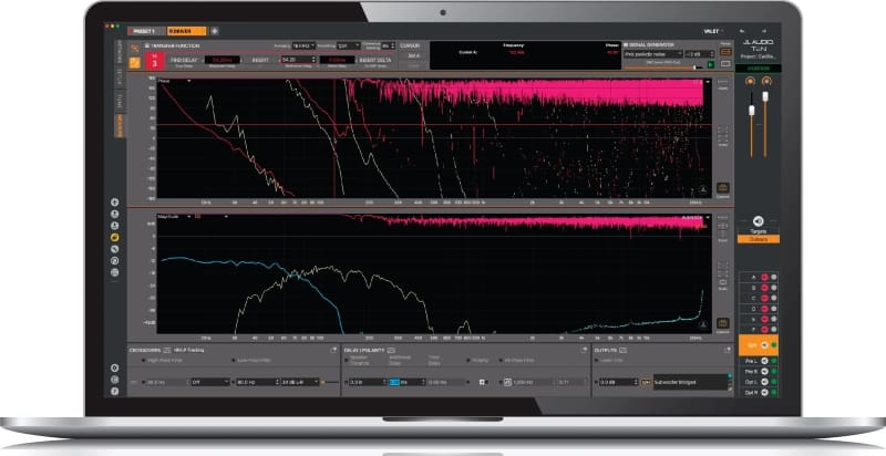
The third and most accurate way to evaluate the phase between two speakers operating in adjacent frequency bands is to take measurements of the acoustic response using an audio analyzer system that includes phase evaluation. This can be done with Room EQ Wizard, Open Sound Meter or Smaart and a good USB audio interface, or with a dedicated measurement system like the JL Audio MAX or Audison bit Tune. These solutions are best used with a digital signal processor that will allow the technician to fine-tune the arrival time of the signals from the main speakers and the subwoofer. Adjusting the arrival time can dramatically improve the system’s performance. This alignment is key to getting the “upfront bass” sensation many audio enthusiasts crave.
Speaker Polarity and Phase Is Complicated
Our example of a -12 dB/octave Butterworth alignment crossover has served us well in answering this specific question about speaker polarity. However, the topic is much more complicated. First, different crossover slopes and alignments result in different phase shifts at the crossover frequency. A -18 dB/octave Butterworth filter results in 270 degrees of phase shift at the crossover point, making easily predictive summing very difficult. However, a -24 dB/octave Linkwitz-Riley filter is 360 degrees at the crossover point and requires no adjustments.
Further complications ensue when we consider the speakers used in the audio system and their installation. For example, if a door woofer rolls off at -6 dB/octave at a frequency similar to the crossover point, the phase shift from the crossover combines with that of the speaker. You’ll often see passive crossover networks between midrange drivers and tweeters that use different slopes. If your goal is the best performance possible, then scientific analysis of the amplitude and phase of each driver at the listening position is the only option.
If you want the best performance possible from your car audio system, drop by a local specialty mobile enhancement retailer and have them design, install and calibrate your audio system. If they have tools to measure phase, they can fine-tune the relationship between all the speakers in the system with impressive accuracy. If you already have a system installed in your vehicle, something as simple as reversing the subwoofer polarity can offer a dramatic performance improvement.
