 When people are looking at purchasing a car audio amplifier, the specification they check most often is how much power it can produce. Power is rated in watts – a universal unit of measurement of power. In this article, we explain what a watt is, and how it is measured – both the correct and incorrect way.
Dictionary Time!
 Let’s get the formal definition of a watt out of the way first. A watt is an SI (Systéme International) unit of the measurement of power. The power does not have to be electrical. In fact, the unit watt was named after James Watt and created to quantify the work a steam engine could do. In that kinetic application, a watt was the work done when the velocity of an object was moving steadily at 1 meter per second with a force of 1 newton opposing it. When referring to an electrical motor, 1 horsepower equals 746 watts.
As much fun as talking about horsepower is, we are car audio enthusiasts, so let’s get back on track with an explanation of the electrical watt.
In electrical terms, a watt is a transfer of 1 joule of energy over a period of 1 second. The next logical question is what is a joule? A joule is yet another SI unit of measurement, and it defines the amount of work required to move a charge of 1 coulomb through an electrical potential of 1 volt. Yes, the question now moves to the coulomb – what in the world is that? A coulomb is a unit of electrical charge – and is equal to -6.242 x 10^18 electrons.
Lost yet? Don’t fret; we are just appeasing the math and measurement nerds among us. Let’s break this down to what matters.
When we want to use electricity to do work, we have to flow electrons through a device like a filament, motor or voice coil. The result will be, in the case of a speaker, that the magnetic field created by the flow of electrons will cause the voice coil to be attracted to or repelled from the fixed magnet in our speaker. When we flow more electrons, more work is done, and the speaker moves farther toward or away from the magnet.
Power Math
Here is where we start to talk about power equations. There are three common methods of calculating the power in a circuit – but we need to know the values of other variables such as voltage, resistance or amperage. Any two of these variables can be used to calculate the power done in a circuit. Here are the equations:
 If we have a circuit with a resistance of 4 ohms and we apply a voltage to it with a potential of 10 volts, then we have 25 watts of power. Increasing that voltage to 20 volts means the power available is now 100 watts. We can substitute and rearrange the variables in the equations above to figure out any other variable – it’s simple algebra.
Measuring Power
When a technician has an amplifier on a test bench and wants to measure power, the technician typically connects the amp to a bank of high-power load resistors, then measures the output of the amplifier when the signal has reached a distortion level of 1%. The measurement taken is voltage. Most often, we assume the load is not variable. Let’s say we measure 44 Volts RMS out of an amplifier and we have the amp connected to a 2 ohm load. That works out to 968 watts. It’s very simple and very repeatable – but it doesn’t work in the real world. Let’s look at why.
Resistance versus Reactance
This is going to get a bit technical. Audio signals are alternating current (AC) signals. AC signals are required to make the speaker cone move back and forth from its rest position, but they make power measurement much more complicated. The way conductors and loads react to AC signals is different from direct current (DC) signals.
Because AC signals change direction, the polarity of the magnetic fields they create also changes direction. Trying to change the polarity of magnetic fields wreaks havoc with the behavior of current flow. Once current gets flowing and sets up a magnetic field, it doesn’t like to stop. Imagine a DC voltage – all the electrons are moving in the same direction all the time. They are happy and have no complaints. When it comes to AC signals, though, that flow of electrons has to change directions. With a 20 k Hz signal, the change of directions happens 20,000 times a second. Electrons are lazy – they like to keep doing what they were doing. Because of this, they oppose a change of direction.
An inductor is truly nothing more than a coil of wire. We see inductors in passive crossover networks and the filter stages of Class D amplifiers. When electrons are flowing through an inductor, they set up a strong magnetic field. When you take away the voltage source, the electrons try to keep flowing. In fact, if you have seen a relay with a diode connected to it, that diode is there to give that flow of electrons somewhere to go, other than back into the circuit that was controlling the function of the relay.
 When we apply an AC signal to an inductor, the higher the frequency, the harder it is to change the direction of the flow of electrons. The resistance to the flow of alternating current is called inductive reactance. Think of it as resistance, but only applicable to AC signals. Inductors oppose a change in current flow. If we disconnect our alternating current source and measure the DC resistance of an inductor with a multimeter, the number we see on the screen is the resistance. To measure the reactance of an inductor, we need a device that can apply an AC signal and measure the effective voltage drop across the inductor.
The formula to calculate inductive reactance is Xl = 2 x pi x F x L, where F is the frequency of the applied AC signal, L is the inductance value of the inductor measured in henries and Xl is the inductive reactance in ohms. You can see that inductance increases with frequency, as we mentioned earlier.
The voice coil of a speaker is and acts as an inductor.
Current and Voltage
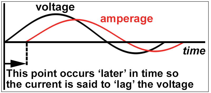
We have more bad news for you. Because an inductor opposes the change in current flow, a timing error arises. Timing of what, you ask? The relative time between the AC voltage across the inductor and the AC value of the current flowing in the inductor. In a perfect inductor (one with no DC resistance), the current through the inductor lags the voltage across the inductor by 90 degrees or ¼ of the frequency of the signal being passed through.
Let that sink in for a second, then think back to our equations for power. Power is voltage times current. But what if the current peak isn’t happening at the same time as the voltage peak? We can’t simply multiply the two numbers together to get the power in the circuit. Worse, the amount of time that the current lags voltage depends on the DC resistance of the inductor and the inductive reactance – for most car audio speakers, the DC resistance is usually somewhere between 2 and 8 ohms. The inductance is in between 0.04 mH for a high-quality tweeter to more than 5 mH for a big subwoofer.
There’s one more challenge: The inductance changes depending on the drive level of the speaker and the position of the speaker cone.
We’re sure you agree – It’s all very complicated, but don’t give up just yet.
How do we measure the real power in an AC circuit? There are a couple of ways. We can measure instantaneous current and voltage at a very high sampling rate and multiply them together. The sampling rate would have to be 20 or 30 times the frequency we measure to be reasonably accurate. We can also use conventional meters to measure the amount of current and voltage in the circuit, then use a Phase Angle Meter to find the relative relationship between the two. Pretty much none of us have a standalone phase angle meter in our toolboxes. What we can’t do is just multiply voltage and current times each other.
Those SPL Guys And Watts
If you are reading this, then you likely roam the Internet with some frequency. You have undoubtedly seen SPL enthusiasts attempt to measure the power produced by their amplifiers by “clamping”’ it. They connect a current clamp to one of the speaker wires coming out of the amp and put a voltmeter across the terminals of the amplifier.
This creates three problems:
- They should connect the voltmeter to the speaker terminals. Because of the high current flow, the resistance in speaker wire can waste a measurable amount of power.
- With a voltmeter and current clamp, we don’t know the phase relationship between the current flowing through the voice coils and the voltage across the voice coil.
- They typically perform these tests at extremely high power levels. The massive amounts of power heat up the voice coils quickly. This heat also increases their resistance quickly. This increase in resistance will cause the current flowing through the speaker to decrease. If the connected current clamp is in “peak hold” mode, it will store a peak reading of the initial current flowing through the voice coil. The reduction in current flow eases the load on the amplifier power supply and allows it to produce more voltage. As current decreases, the voltage out of the amplifier may increase, giving a false reading to the voltmeter in peak hold mode. This heating and resistance increase can happen in a matter of seconds.
If you thought our definition of the watt was complicated, then explaining how to calculate power in a reactive load would push you over the edge, so we won’t explain it all. That’s a topic saved for college or university courses on AC power. What we will do is provide a solution for making complicated power measurements.
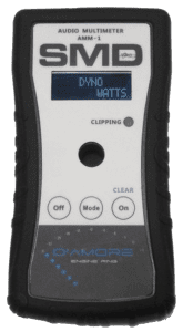 The reality is when it comes to measuring power out of an amplifier while connected to a speaker, getting accurate results is very difficult. A few companies produce car audio power meters. The most popular unit is the D’Amore Engineering AMM-1. The AMM-1 is a handheld meter that simultaneously measures current and voltage, and calculates the phase angle between them to provide an accurate power measurement. The AMM-1 will show you how much real-world power your amplifier is making. (Please don’t cry if it’s less than you thought.)
The AMM-1 can also show volt-amps. Volt-amps are calculated by multiplying current times the voltage. You can also see the phase angle of the load on yet another screen. If you are serious about measuring power when an amplifier is driving a reactive load like a speaker, then this is the tool you need.
What You Need to Know
When you are shopping for an amplifier, the numbers you usually see quoted are measured into resistive loads. Most amplifiers have no problem with driving reactive loads, so you can trust the published numbers, as long as the distortion specification is clearly defined.
 The CEA-2006A (now called CTA-2006A) specification for power measurement defines the maximum signal distortion during measurement as being 1%, and no more than 14.4 volts can be supplying the amp. Comparing power specs using this standard has leveled the playing field in the car audio industry.
We will look at some other very important amplifier specifications in another article. These other specifications may, in fact, be more important to choosing the right amp for your system than how much power the amp makes. Until then, drop into your local car audio specialist retailer to find out about the latest amplifiers available for your system. There are some amazing new amps on the market with a lot of cool features.
Happy listening!

Leave a Reply