For as long as I can remember, the ubiquitous ground loop isolator has been a staple of the car audio industry. In recent years, the need for these noise-elimination devices has decreased dramatically, thanks to the inclusion of balanced or differential input circuits on amplifiers or signal processors. Let’s dissect an isolator and make a few measurements to see how adding one affects the performance of a car audio system.
What Is a Ground Loop Isolator?
If you’ve ever experienced a car stereo system with an annoying buzz or whistle that changes with engine speed, you’ve likely witnessed a ground loop. A ground loop in the context of audio systems happens where there is a difference in ground potential (or voltage) between two audio components. This voltage difference results in current flowing through the shield of a conductor in an attempt to equalize this unwanted voltage difference. Unfortunately, that voltage will contain noise from the charging system (alternator), which gets confused with an audio signal and, thus, amplified and sent to the speakers.
Breaking a ground loop is as simple as cutting the conductor path between the two objects. In the case of an audio system, that would mean cutting the ground shield in a coaxial interconnect. While simple in concept, cutting the shield and using the center pin alone can cause issues. So, to keep the signal intact relative to the ground reference, we use an isolation transformer on the output of the source and the input of the amplifier or a signal processor.
How Does a Transformer Work?
If you took physics in high school, you know that when current flows through a conductor, it produces a magnetic field around it. In a transformer, the primary winding connected to the audio source is wrapped repeatedly around a magnetically conductive core. The secondary winding that connects to the amplifier wraps around the same core. The AC audio signal from the primary winding creates oscillating magnetic fields in the core. Those magnetic fields cause current to flow in the secondary winding. Now, we have a path for the audio signal isolated by a magnetic field. This isolation prevents the ground loop as DC (direct current) can pass through a transformer.
Problems with Audio Transformers
While theoretically ideal, some significant issues exist with transformers regarding passing audio signals. This article examined how poorly transformer-based line output converters work.
To start, all transformers have losses. This means that the amount of current you put into them does not equal the amount you get out. Second, they don’t typically function equally for all frequencies. As such, they may alter the perceived frequency response of an audio signal that passes through the devices. Lastly, they add distortion. We’ll stop here momentarily and remind our readers that adding distortion is not the same as clipping. Distortion refers to the addition of unwanted information to a signal. In most cases, the distortion is harmonics of the audio frequencies in the original signal. Our testing will make this statement much more straightforward to understand.
That Doesn’t Even Make Sense
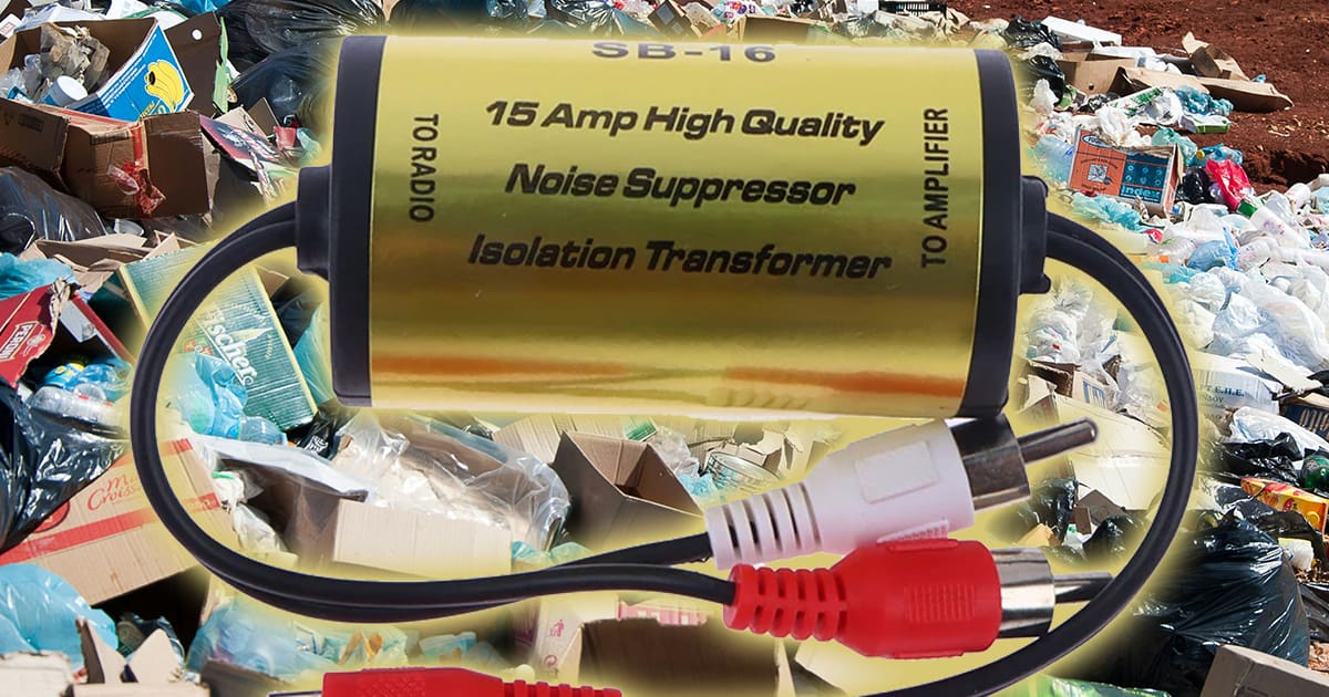
We hunted down a sample of what would be a typical transformer-based isolator. This particular unit includes an absolutely bizarre statement on the product label with a claim that it can handle 15 amps of current. Almost no current flows through RCA interconnects. At most, with a low impedance output and input, there might be a few milliamps at the highest volume levels. Why this product needs to claim it can handle 15 amps makes less than no sense. Chances are, the factory carried that characteristic from a noise filter they also produce. Nevertheless, we didn’t want to pass on an opportunity to point out something so illogical.
Setting a Reference for Quality
We need a reference to understand what adding an isolator does to an audio signal. For this, we’re going to use a high-quality amplifier. This particular amplifier has a Class D output stage but dramatically outperforms most Class AB amplifiers in all regards. We’ll look at four measurements to quantify the amplifiers’ performance to establish a benchmark. Then, we’ll wire the isolator into the system and repeat those measurements. We’re going to use this configuration since amplifiers with different input impedances can affect how much current flows through the transformers. Changes in current levels can further affect quality.
Signal Loss
We’ll start by measuring how much signal is lost when we add the ground loop isolator to the circuit. To test this, we’ll note how much voltage the signal generator needs to provide to produce a 2-volt output from the amplifier. When we add the isolator, we can look at the new output voltage to determine the losses.
Feeding the amplifier 105 millivolts with the gain at its minimum setting produces 1.001 volt of output. We performed two measurements to quantify losses in the isolator. We measured the amp’s output separately with the isolator’s left and right channels.
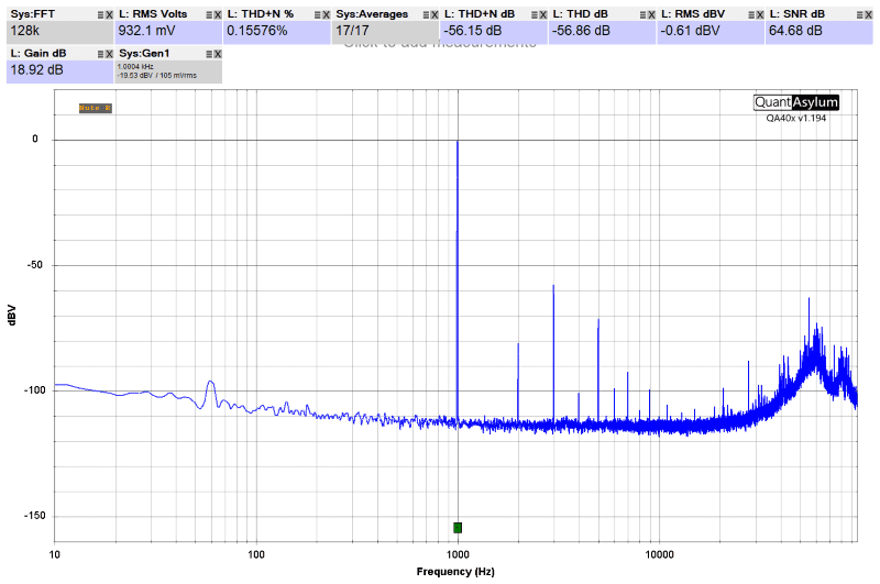
So, we’re losing about 6.5% of the signal from our source as it travels through the isolator. Worse, there is some imbalance in the losses. That’s not horrific, but it means your installer must turn the gain up a bit. A second issue is that the left channel drops by 6.27%, while the right is down 6.88%. This isn’t a dramatic difference, but unchecked, it could move the soundstage and imaging to the left.
Single-Frequency Harmonic Distortion
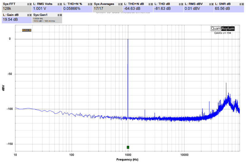
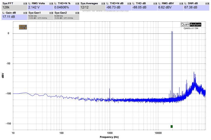
The second measurement we’ll make is to look at the spectral content of a 1-kHz sine wave played through the amplifier. This graph will show us the amplitude of the harmonics of the signal.
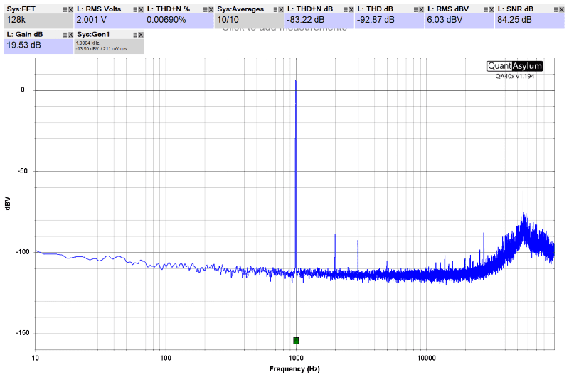
The graph above shows a 1-kHz test tone played at 2.001 volts. The small spikes at the bottom of the graph at 2 and 3 kHz are harmonic distortion products. What matters in analyzing this data is the amplitude of those harmonics. In this measurement, they add together to a level that’s 92.87 dB below the fundamental signal. That works out to 0.00227% THD.
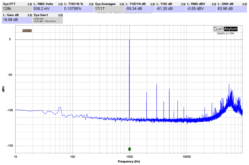
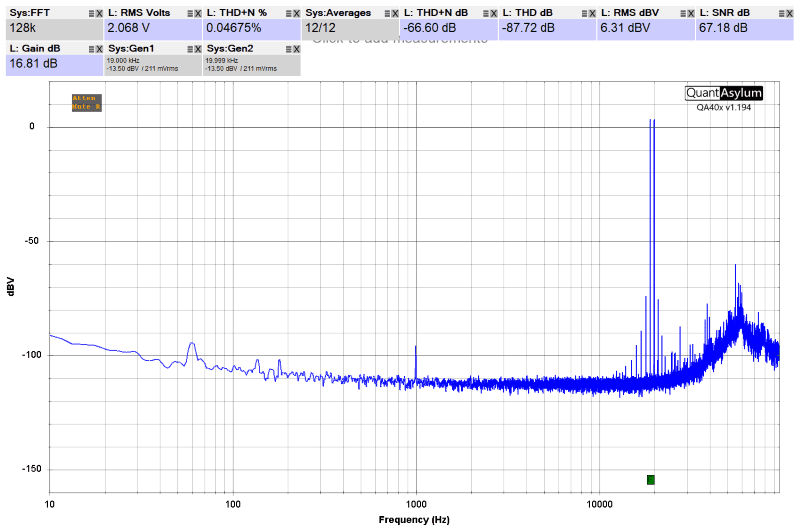
Now, let’s add the isolator in line with the signal from the function generator and repeat the measurement.
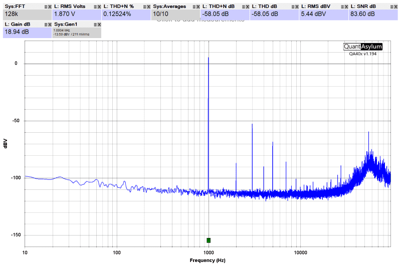
The amplitude of the second-order harmonic at 2 kHz increased a tiny bit. However, the third-order harmonic jumped from a level that was just below -90 dBV to a scary -52 dBV. That’s about 40 times more unwanted information. Further, we can now see fourth-, fifth-, sixth- and seventh-order harmonics. Their sum is now only 58.05 dB below the test tone, which equals 0.125% THD. That’s a stunningly lousy performance.
Frequency-Dependent Harmonic Distortion
If you thought the 1-kHz test was terrible, don’t go anywhere. Let’s measure the harmonic distortion level of the amplifier at different frequencies. We’ll have the audio analyzer perform distortion measurements at various frequencies and plot them across the audio spectrum.
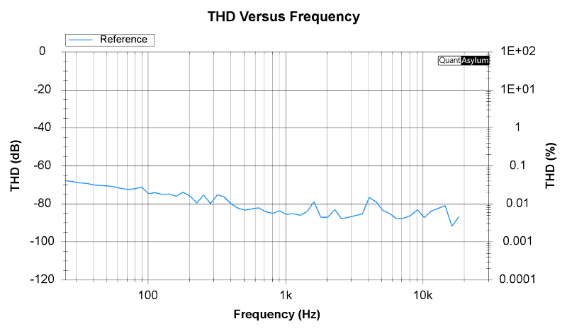
As you can see, the amplifier performs quite well at all frequencies. Let’s repeat the measurement with the isolator installed between the function generator and the amp.
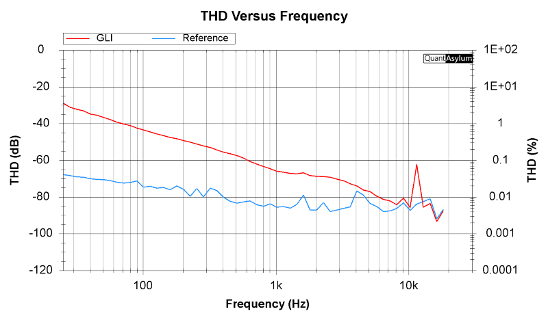
If you thought the 0.125% THD measurement at 1 kHz was terrible, look at what happens at lower frequencies. The signal contains more than 1% THD at all frequencies below 70 Hz. If you want the bass in your car audio system to sound terrible, adding an isolator that uses transformers is the way to do it!
Intermodulation Distortion
The subsequent measurement we’ll make quantifies the intermodulation distortion performance of this reference amplifier. Intermodulation distortion happens when two frequencies play simultaneously. Additional unwanted audio content is added at frequencies that are the difference between the two fundamental frequencies. For example, if we play 3- and 4-kHz tones, we might see frequencies added on either side of those fundamental tones, spaced apart at 1-kHz steps. The 1-kHz value is the difference between 3 and 4 kHz. For our example, we might see unwanted content added at 1 and 2 kHz, as well as 5 and 6 kHz.
We will use the International Telecommunication Union standard for measuring intermodulation distortion for this test. In this test, we play 19- and 20-kHz test tones, then look at the addition of unwanted information on either side of those frequencies.
This measurement shows a tone added at 18 kHz at about -95 dBV and a second at 17 kHz at -100 dBV on the low side. On the high side, there are 21- and 22-kHz tones at about -98 and -99 dBV, respectively. These numbers would be considered a very good measurement.
If we look at this second measurement, we can see the amplitude of the 18-kHz tone has jumped to about -74 dBV, and the 17-kHz tone is -89 dBV. The 21-kHz tone is -76 dBV and the 22-kHz is at -92 dBV. Several additional tones are visible above the noise floor on both sides of the signal. These numbers represent a moderately lousy performance for an amplifier, and for an add-on component to cause this is unacceptable.
Frequency Response Variations
Last but certainly not least, we will examine how adding a GLI can affect frequency response. While all the other measurements are important, the most significant and easily perceptible change is in frequency response. Let’s start by measuring the performance of our reference amplifier.
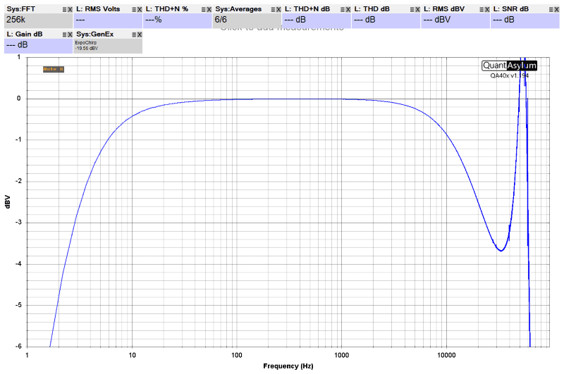
The chart above shows that the amp has -3 dB tolerances at a mind-boggling 2.8 hertz on the bottom end and 24 kHz at high frequencies. These are, once again, excellent measurements. Now, let’s add that pesky isolator, shall we?
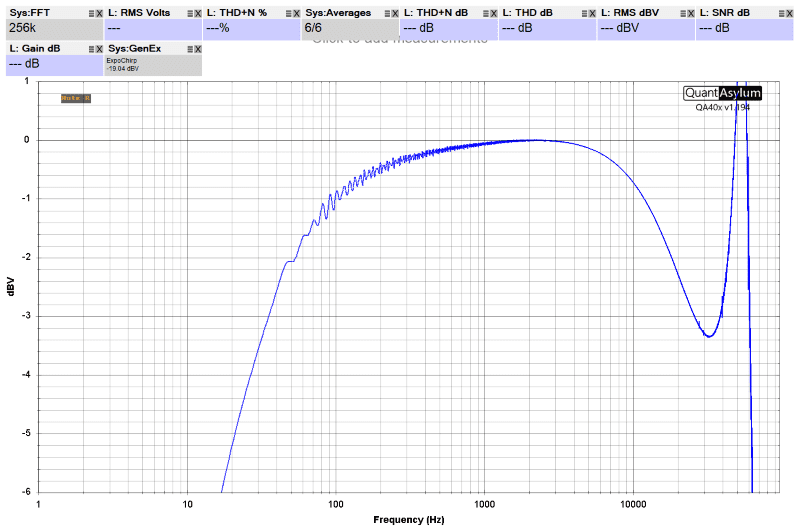
It’s clear to see that the isolator had a very negative effect on the frequency response. The -3 dB point on the bottom end is now at about 46 Hz, and the GLI attenuates all frequencies below roughly 2.2 kHz. The audio system would sound more like a transistor table radio than a full, rich audio system.
Proper Equipment Prevents Ground Loops
There’s no debating that adding a ground loop isolator of this type will negatively affect the performance of your car’s audio system. This leads to the question, what options exist if you have a noise problem? The ideal solution is to use car audio equipment that has differential inputs. We’ve written two articles that describe simple measurements that will let anyone know whether an amplifier or signal processor has this circuitry.
We understand that swapping out equipment is often complex and potentially expensive. Adding a high-quality line output converter can be the solution in those instances. Most high-quality electronic line output converters can work as line drivers with full ground reference isolation properties. We’ll refer you to our Bench Brawl article that compares transformer-based converters to electronic units.
Finally, changing how a system is wired can help resolve ground loop noise issues. Sourcing ground from the same location as the amplifier is one option. If you have a noise problem, drop by a reputable specialty mobile enhancement retailer and ask for help. They should have the tools, training and products to resolve the issue.
