Our Car Audio Masterclass series offers a comprehensive introduction to the essential concepts of car audio systems, covering everything from basic terminology to advanced measurement techniques. To learn more, check out the other articles in the series:
- Car Audio Masterclass 101.1 – Audio Basics: Learn key audio terms and concepts.
- Car Audio Masterclass 101.2 – Understanding Basic Electricity: Explore voltage, current, and resistance.
- Car Audio Masterclass 101.3 – Electric Circuits: Understand series and parallel circuits.
- Car Audio Masterclass 101.4 – Magnetism: Discover the role of magnetism in speakers.
- Car Audio Masterclass 101.6 – AC Calculations: Dive into AC waveform calculations.
- Car Audio Masterclass 101.7 – The Decibel: Learn about decibel measurements.
- Car Audio Masterclass 101.8 – Speakers, Power, and SPL: Understand speaker power and sound levels.
- Car Audio Masterclass 101.9 – Time and Frequency Domain Measurement: Explore frequency and time measurements.
- Car Audio Masterclass 101.10 – Digital Multimeter: Learn to use a multimeter in car audio.
So far, the Car Audio Masterclass series has discussed electricity, explained Ohm’s law, discussed the basic concepts of sound and examined magnetism. To move forward, we must explore a more complicated aspect of electricity—direct and alternating current. Once again, understanding these concepts is crucial to understanding how car audio products like radios, amplifiers, signal processors, speakers and subwoofers work.
What Is Direct Current?
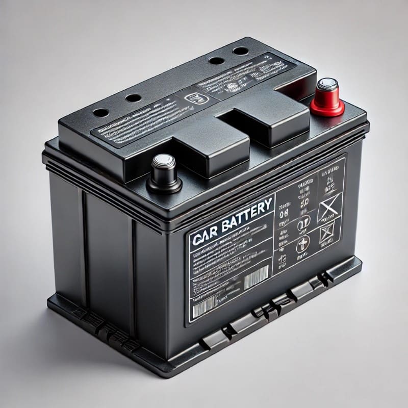
We’ll start by explaining direct current, also called DC voltages. Just as we did with the power source we described in lesson 101.2, Electricity fundamentals; we can think of a battery as having a reserve of electrons. When we wire conductors, switches and loads to that battery, current flows from one terminal to the other. In conventional electrical theory, we talk about power flowing from the positive post to the negative. When discussing electron theory, we discuss negatively charged electrons moving from the negative terminal to the positive.
In either scenario, the flow of electrons is in one direction, no matter how much the load changes. We call this Direct Current, or DC. Further, even if the supply voltage fluctuates in amplitude, we always refer to the power source (battery, for example) as a DC source.
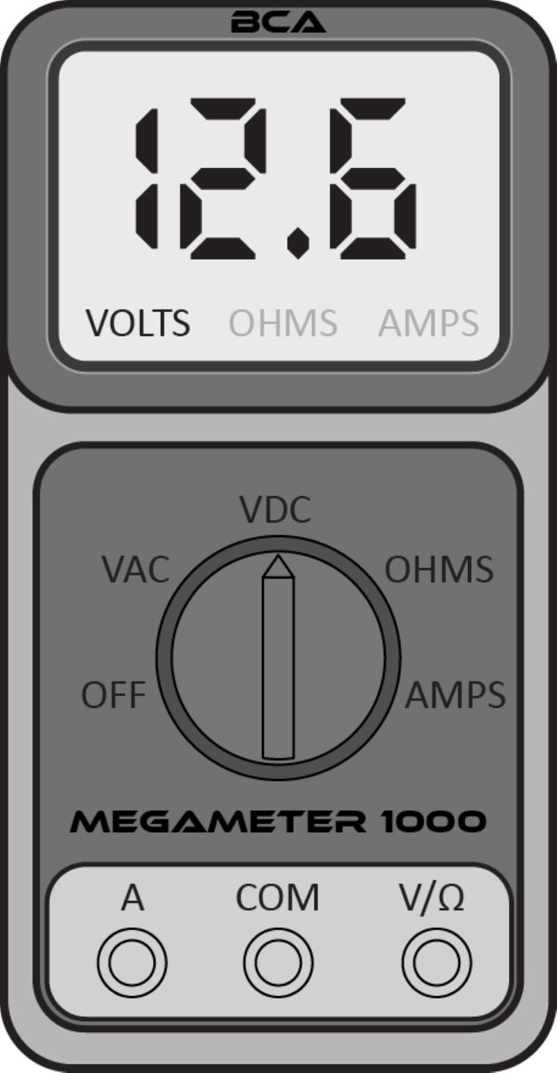
If we connect a multimeter set to DC volts to the battery, we will see 12.6 on the screen.
If we measure a DC voltage using an oscilloscope, we see a solid line travel across the screen at a fixed voltage. The BCA Megascope shows a violet trace at 12.6 volts. This would be what we see if we connected the test lead of an oscilloscope to a car battery.

Direct Current – A Brief History
The first power sources were batteries, or, more accurately, Alessandro Volta’s Voltaic Pile in 1799. This simple power source had layers of zinc and copper separated by cardboard discs. The assembly was soaked in salt water. Like the AAA batteries in a TV remote or the 12.6-volt battery in your car or truck, the Voltaic Pile produced a constant voltage. Thus, any load connected to it was provided with DC current.

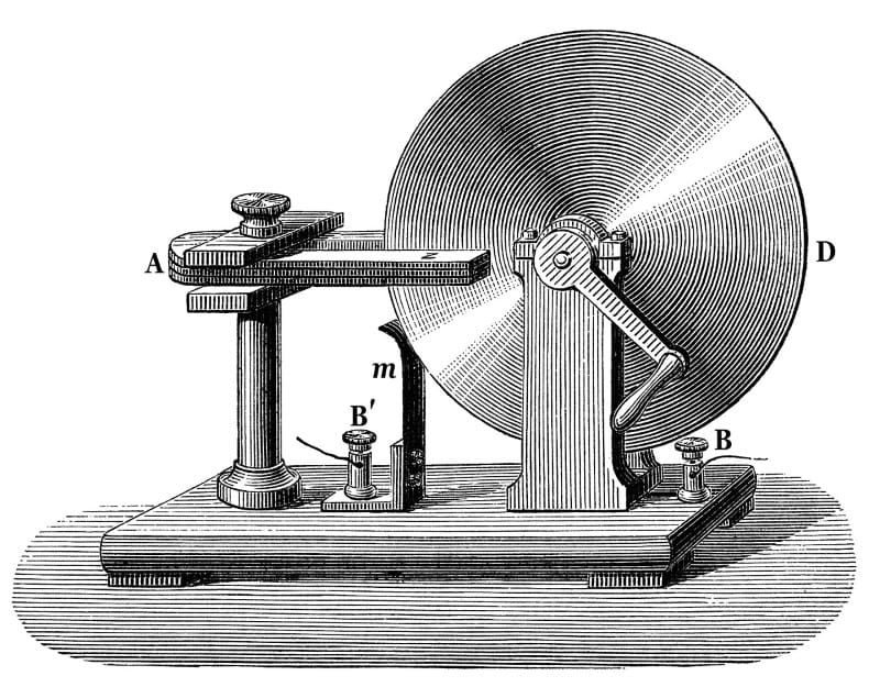
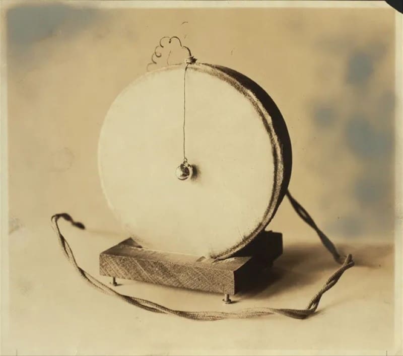
Michael Faraday created the first generator around 1831. This device created voltage by spinning a copper wheel between the poles of a horseshoe magnet.
The Origins of Alternating Current
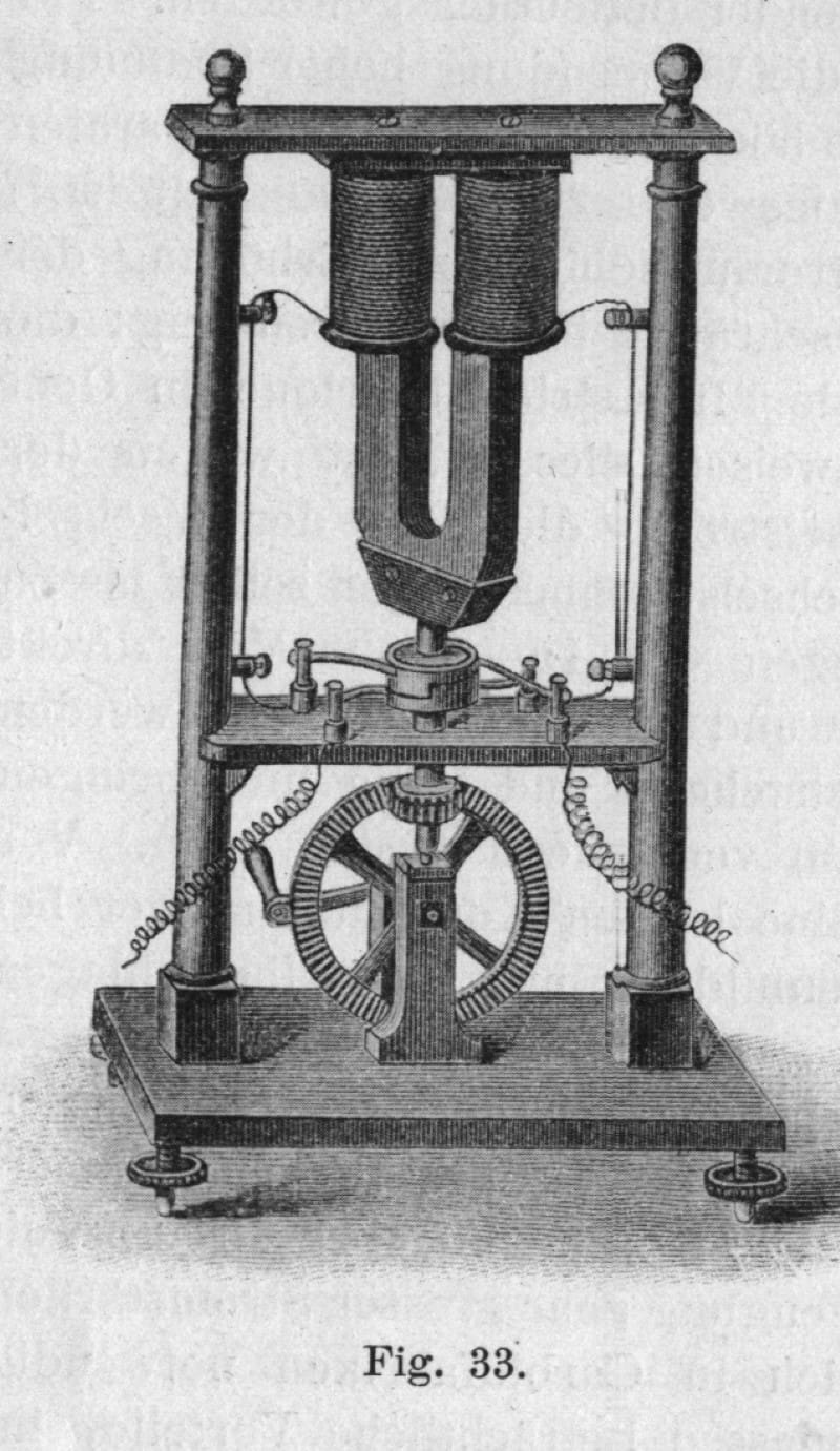
The Faraday Disc design was evolved by the company Hippolyte Pixie into what would become the first alternator. Unlike the Faraday Disc, this device produced a voltage that would alternate from positive to negative as the poles of a magnet passed over two iron cores wrapped in copper wire. As the magnet’s south pole passed by one iron core, it would induce a voltage in one direction (or polarity). As the north power passed, it induced an opposite polarity voltage.
As you can imagine, scientists quickly learned about magnetic fields in the generator and the magneto. Fast forwarding a bit, this knowledge led to the creation of the transformer. A transformer is an iron core with two windings of wire. When AC voltage is applied to one wire, it creates a magnetic field in the iron core. That field induces a voltage on the second winding. Ignoring some losses, we can say that if we have 20 windings of wire on the input winding to the transformer and 40 windings on the output winding, we’ll get twice as much voltage on the output.
By the 1850s, Arc lamps were installed in museums and lighthouses. However, delivering power to these lights was difficult, as no established distribution system existed. Fast forward to the 1880s and 1890s and the War of the Currents. At that time, street lights operated on moderately high voltage AC power. Direct Current was being used for incandescent indoor lighting. The latter was marketed and sold by Thomas Edison’s company. In 1886, George Westinghouse’s company introduced an AC system for indoor lighting that used transformers to step the high voltages used outdoors into something more reasonable for use inside a home.
Power Calculations and Current
Before declaring the winner, we must return to lesson 101.2 and discuss power. Crucially, we know that power can be calculated with the formula P = I^2 x R. When attempting to run large amounts of power over long distances, as you’d find from generators to homes and offices, large amounts of current and even relatively minute cable resistance cause a lot of power loss in the wire. For example, the transformers on the street in front of your home are likely fed with 7200 volts.
The feed to your home is a pair of 120-volt lines, each fused at 100 amps. Assuming that eight homes are fed from each subdivision transformer, it must provide up to 800 amps of current. That’s equivalent to almost 10,000 watts of power. If the power company ran wires a mile rated to carry 800 amps of current, the wire would need to be sized at 2000 kcmil. To put that into perspective, including the insulation, most adults wouldn’t be able to wrap their thumb and index finger around a wire that large.

Now, if we use a transformer to convert the input voltage to the transformer from 120 volts to 7200 volts, the electric company only needs to supply 13.3 amps of current. The result is that a 2/0 conductor can run a mile with 13.3 amps of current with roughly the same losses when using 7200 volts rather than 120.
Power Transformers Reduce Power Waste
The ability to step AC voltages up and down using transformers allows electric companies to transmit power over incredible distances with minimal losses. We used Google Maps to look at the main electric feed in our city. It runs just under 15 miles to the next large transformer station and is fed from a station 7.5 miles in the other direction. These lines likely operate at 115,000 volts.
Westinghouse won the War of Currents because it could easily increase or decrease AC power with relatively cost-effective solutions like transformers. AC power distribution is the standard worldwide.

AC Audio Signals
Let’s jump back to lesson 101.1, in which we discussed sound variations in pressure. The buzz of a mosquito might be 400 hertz. This means that little pressure increases and decreases, which change 400 times a second, are produced by these little bloodthirsty beasts. If we could convert the pressure waves into an electrical signal, we’d see that signal oscillate at the same frequency.
In 1827, Sir Charles Wheatstone coined the phrase microphone. Wheatstone was among the first scientists to recognize that “waves transmitted sound through mediums.” With a goal of transmitting sound over long distances using wires as an advancement of the telegraph, he knew that a device was required to reliably convert sound into an electric signal. Around 1876, Emile Berliner, who was working with Thomas Edison, created the first microphone. This quickly led to the invention of the telephone.
Magnetic Fields and Current
The knowledge that moving a wire through a magnetic field to induce current flow also works in the reverse direction. If we have a moving magnetic field and we bring it into the vicinity of a wire, that will also induce current. A microphone is simply a diaphragm with a coil of wire wrapped around a fixed magnet. When sound, which is simply vibrations, moves the diaphragm, the coil of wire moves relative to the magnet and current begins to flow.
The current amount depends on how much the diaphragm moves, which is analogous to amplitude, or volume. The speed at which the diaphragm moves is proportional to the frequency of the sound affecting it. In short, this simple device can convert pressure waves into electrical waves. As a tease for an upcoming article, it should be no surprise that a speaker converts electrical waveforms into sound using the opposite principle.
Fundamentals of Alternating Current Signals
Before we wrap up, we should look at some properties of alternating current signals. In the context of audio, we use these waveforms to carry audio information from one component to another. This might be from the tuner inside your radio to the little amplifier chip or from the amplifier to the speaker.
The amplitude of the waveform determines the loudness of the signal. The signal’s frequency content represents the original sound’s frequency content. It’s crucial to understand that AC signals can contain multiple frequencies. Unlike the 120-volt 60-hertz sinusoidal waveform at the electrical outlets in our homes and offices, audio signals contain information from just a few hertz to well beyond the range of human hearing (20 kHz). Most of these frequencies can exist at some amplitude simultaneously.
Analyzing an AC Waveform
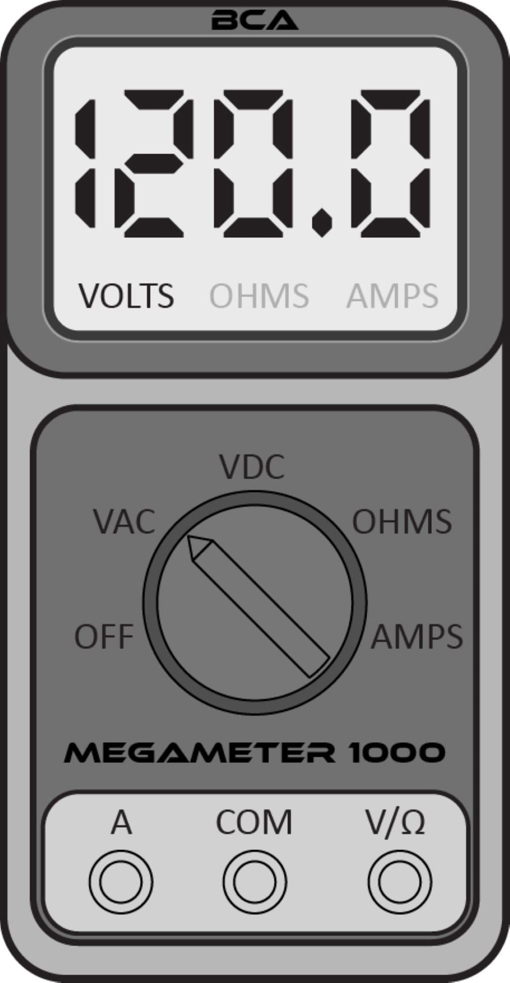
If we use the BCA MegaMeter 1000 on the AC Volts range, we will see a reading similar to what’s shown below.
If we use the BCA Megascope 1000000 to look at the same waveform, we’d see what’s shown in the image below. Please don’t connect your scope to the wall without ensuring the probe you are using is rated for that much voltage. Many aren’t, and this mistake will destroy the scope.
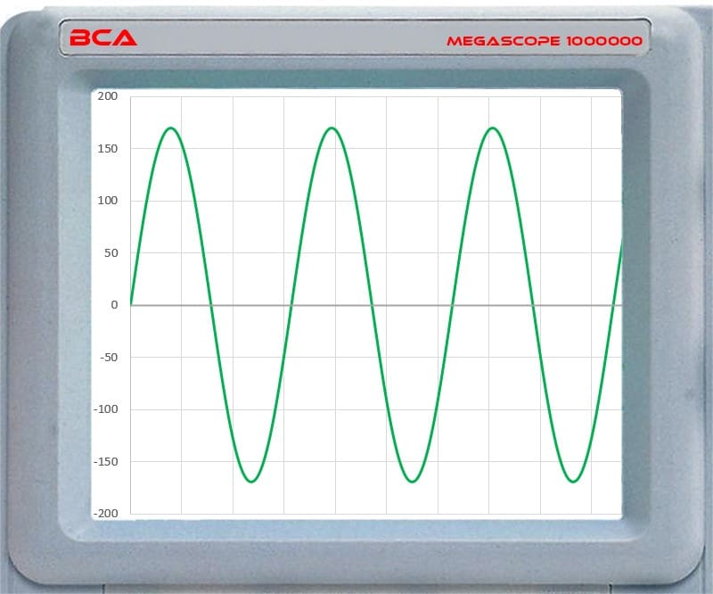
Looking at the image above closely, you’ll see that the waveform oscillates around zero volts. Secondly, the waveform’s peaks are at just under 170 volts. This is a perfect segue into our next lesson about calculations related to alternating current signals.

