There will always be debates about whether a Class D amplifier can sound as good as a Class AB. We’ve proven that it all depends on who designs the amplifier. We also see mumblings about single-ended amps versus full-bridge designs. STMicroelectronics created a different and unexpected way to deliver efficient power. These amplifiers are categorized Class SB and Class SBI. Let’s see if we can explain how they work.
Amplifier Output Device Topologies
Before we dig into the Class SB amplifier, we need to clarify a few things. There are two ways to configure the driver devices (transistors or MOSFETS) to provide large amounts of current to speakers. In a Class A configuration, the output device is halfway on when no audio is playing. The audio signal can modulate the output from its resting point at 50% up to nearly 100% and down to nearly 0%. While extremely linear, these designs are notoriously inefficient and waste large amounts of energy. A Class A amplifier circuit has a maximum efficiency of 25% and only gets worse as the output level decreases from full. Playing nothing at all, a true Class A amplifier wastes half the maximum current delivery capability of the power supply as heat.
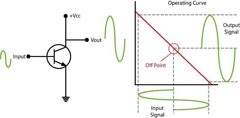
In a Class B amplifier, we dedicate one transistor to the positive half of the audio waveform and a second to the negative half. When no music is playing, the output devices are functionally off.
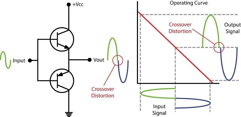
We have to add a little voltage to the output devices so that the transition from one to the other is smooth. Many low-quality amplifiers don’t do this well. In those instances, we’ve seen a little step in the waveform through the transition. This step is called crossover distortion. When executed smoothly, there is no step. This mode of operation is commonly called a Class AB output device configuration. In reality, it’s just a voltage-biased Class B, but there’s clearly no going back on the name now.
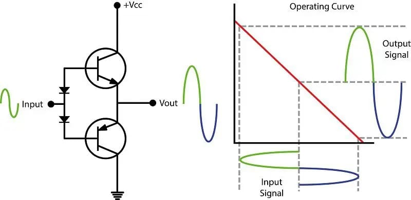
In this context, Class A and Class B are called output device topologies. These are the only two ways output devices can be wired.
Class D Operation
When we talk about Class D amplifiers, we aren’t discussing how the output devices are configured. Class D is a description of the signal used to drive the output devices. Most Class D amplifiers use a Class AB output device configuration.
As you can see in the image below, the analog audio waveform is chopped into little pieces by the Class D driver IC. The width of the spikes relative to the switching frequency represents the output level. Very narrow spikes produce small amounts of output, and very wide spikes produce high output levels.
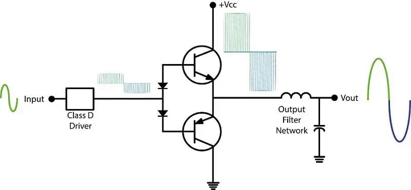
The benefit of Class D operation is that the output devices are switched fully on or off. They spend very little time part-way on. In essence, they block all current flow or allow it all through. Transistors and MOSFET devices are least efficient when they allow half the current through – as we saw in a Class A configuration. The result is a dramatic improvement in efficiency. Many well-engineered Class D amplifiers have 92% total efficiency.
Amplifier Integrated Circuits
Before we go off the rails with Class SB, let’s look at dedicated amplifier ICs. Almost every car radio for the last few decades uses a single chip as an amplifier. These chips typically have four channels of amplification and all the protection circuitry required to prevent DIYers from blowing up their radios. Most IC amplifiers provide 16 to 21 watts of power into 4-ohm loads from each channel.
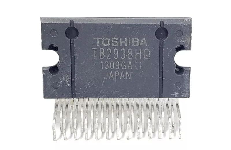
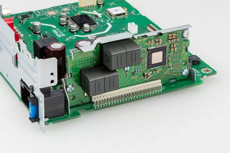
Sony took things further with their High Power radios and used a Texas Instruments IC called the TAS5414C. In their head unit applications, I’ve measured over 42 watts of power from each channel. In what Sony calls their Subwoofer Direct mode, I’ve measured over 76 watts of power.
Bridge-Tied-Load Amplifiers
Most head units have only the vehicle’s battery voltage available to drive the speakers. They don’t typically have step-up power supplies like an amplifier. As such, we can only get about 13.5 or 14 volts across the speaker terminals. This means we are limited to a theoretical maximum of 24.5 watts. In reality, we see a few watts less as some voltage is wasted in the amplifier circuitry.
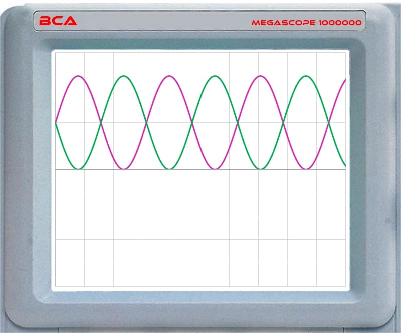
If your installer were to look at the output of a car radio at full power on an oscilloscope, you’d see the following waveforms on the speaker wires.
If we turn the volume down to almost nothing, we’d see the following:
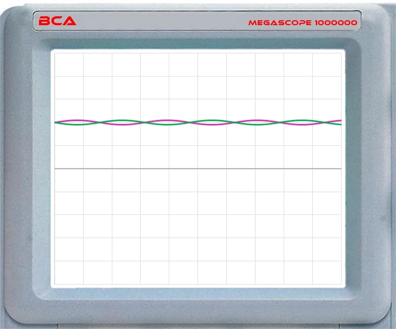
As you can see, both speaker wires have a DC offset voltage. When no audio is playing, there’s about 6 to 6.5 volts present on the speaker wires. Because the voltage is common to both wires, the speaker doesn’t move. The speaker only responds to differences between the wires.
Now, let’s look at a single-ended amplifier. This would be an example of one channel of a typical car audio amplifier.
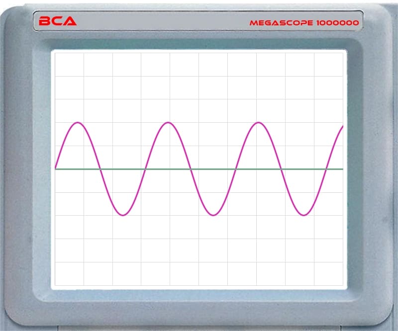
You can see that the probe with the green trace rests at the ground voltage. The probe with the purple trace shows the output voltage swinging from positive to negative and back. The speaker will move forward and rearward to follow the purple waveform.
STMicroelectronics’ Class SB and Class SBI
OK, now you should understand how output-switching devices can be configured and how different waveforms can be used to increase efficiency. STMicroelectronics combined things in the Class SB amplifiers to create something unique and, to put it mildly, creative. STMicroelectronics uses the SB abbreviation for “single-ended bridged” and SBI as “SB improved.” Their claim is Class AB sound quality with a 50% improvement in efficiency.
Class SB amplifiers function as single-ended amplifiers at low to moderate power levels. The waveform sweeps from negative to positive on one speaker lead while the other rests at ground.
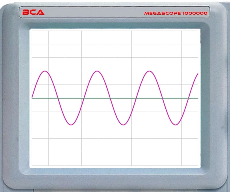
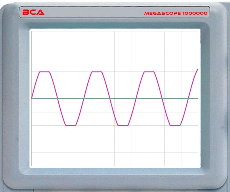
If this were a typical Class AB amplifier, the output waveform would clip if we increased the signal to the amplifier such that the output tried to exceed the rail voltage limits. That would resemble the waveform below.
The Class SB amplifier gets creative when it runs out of rail voltage at high output levels. Check this out.
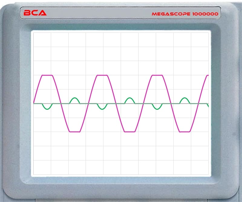
When the main output reaches clipping, the “normally at ground” output increases voltage in the opposite direction. The result is a net increase in amplitude. That’s very creative. In application, having full control over every component in the amplifier is crucial to this design functioning properly. With everything housed in a single IC, STM has that control.
Is a Class SB Amplifier Better?
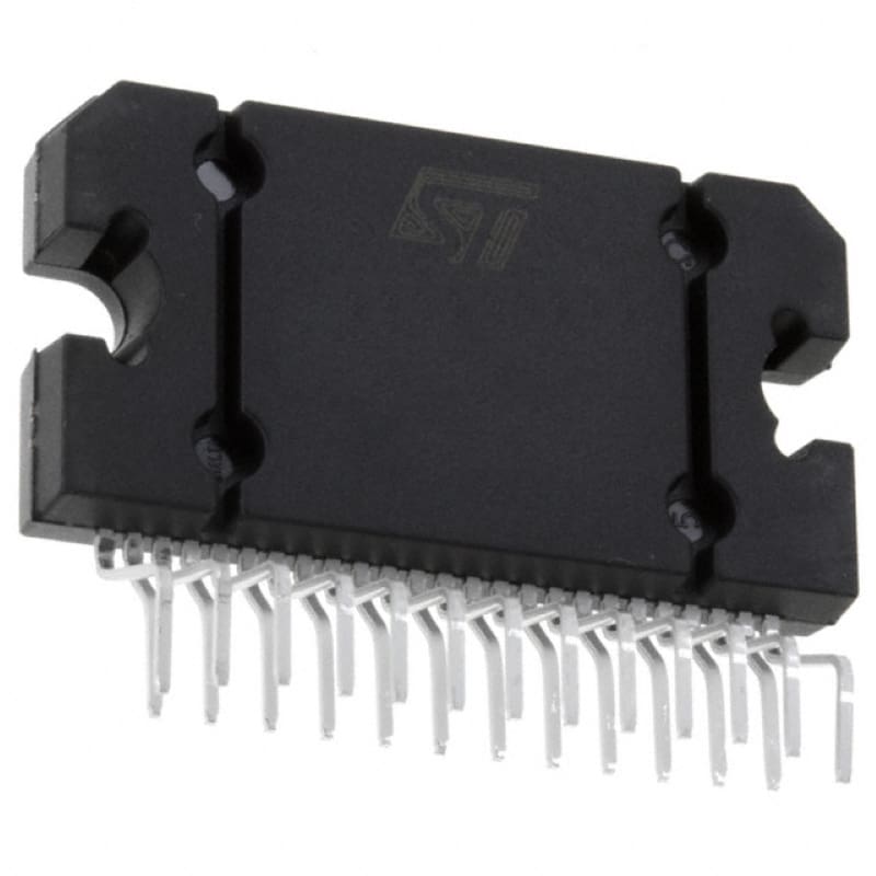
Before claiming that STMicroelectronics has reinvented the car audio amplifier, consider that these ICs have specific applications. They are designed to be compact and efficient. As such, amplifiers created with them at the core can be compact with smaller heatsinks than an equivalent Class AB amplifier. Further, these amplifiers are available with digital inputs. This connectivity makes them ideal for integrating into a closed-network infotainment system, like MOST, AVB or A2B offer. The amplifiers produce about 45 watts of power. This might be good for the main channels of a factory-installed car audio system but won’t be adequate for high-power aftermarket solutions or subwoofers.
What Do Consumers Need to Know about Class SB Amplifiers?
So, what does the typical consumer need to know about Class SB amplifiers? The answer is not much. That said, knowing what new technologies are in use is always good. Class SB amplifiers are primarily a solution for vehicle manufacturers and low- to mid-power audio systems. Installers and technicians must understand how to recognize audio signals from a Class SB amplifier when integrating digital signal processors and new amplifiers into a vehicle. Many, but not all, aftermarket audio upgrades work with Class SB-powered factory-installed source units. If you want more performance from your car audio system, drop by a local specialty mobile enhancement retailer and ask them about the amplifiers, speakers, source units and subwoofers that will deliver the sound you want.
