As we continue our series on what makes one amplifier sound different from another, we will look at intermodulation distortion. As you should know by now, harmonic distortion creates higher frequency components that can make an audio device sound harsh or bright. Intermodulation distortion is typically responsible for unwanted warmth or sloppiness in lower frequencies. When your music loses its snap and impact, even with good speakers, this is the cause.
Instruments Cover a Range of Frequencies
Before discussing intermodulation distortion, we must remember that sounds and music are made up of hundreds or thousands of frequencies. A drum hit, guitar strum or piano note isn’t just a single frequency. Each one contains harmonics that give the instrument its tone or sound. Let’s look at the frequency content of a musician playing a snare drum.
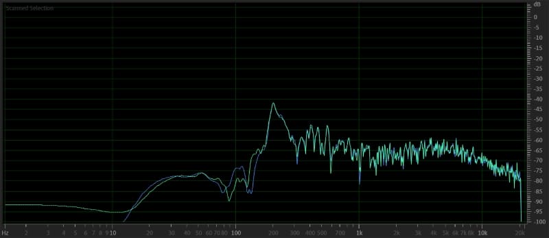
As you can see, this snare drum’s fundamental frequency is 200 Hz. Most people would think of this as a sound primarily reproduced by an audio system’s midbass speakers or woofers. However, for the instrument to sound natural and lifelike, the reproduction must include harmonic content that stretches up to 20 kHz. Without that information, the sound you hear wouldn’t sound like a snare drum. The same goes for every other drum in the kit, as well as guitars, keyboards and vocals. The entire audio spectrum must be covered accurately for the instruments to sound real.
Two Characteristics of Intermodulation Distortion
Let’s get into a more specific analysis of how IMD works. When any two frequencies are played through an audio device (source unit, processor or amplifier), IMD adds additional content spaced at the difference between those frequencies. Let’s use the example of two sounds, one centered at 2 kHz and the second at 2.25 kHz.
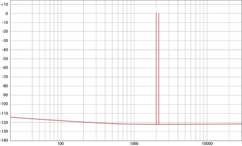
The first piece of unwanted information added to the output of the piece of electronics will be audio content centered at 250 hertz. That’s right: Devices with IMD issues add low-frequency information. Here’s what our discussion looks like so far in the spectral domain. This frequency is determined by the bandwidth between the two fundamental frequencies. In our example, we have 2.25 and 2.0 kHz, so there are 250 hertz between them. We call this the f2-f1 frequency.
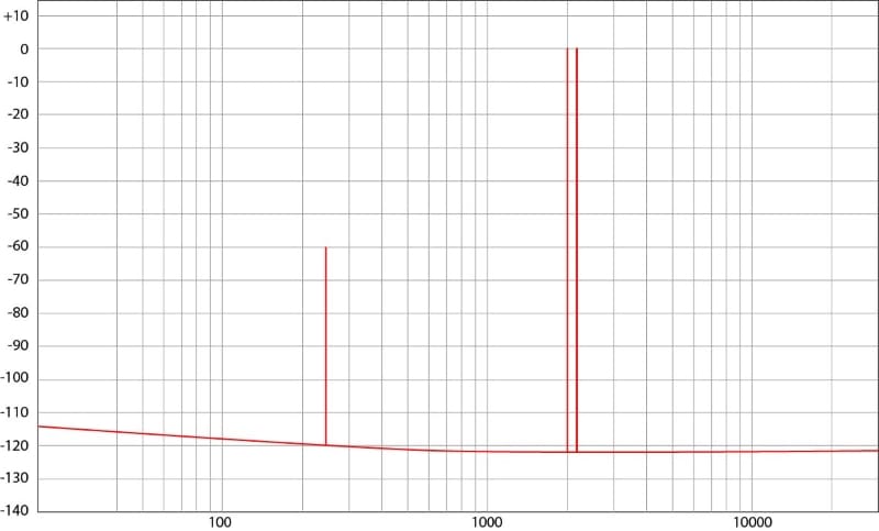
In this example, the f2-f1 frequency has an amplitude of 60 dB below each fundamental frequency. Since the fundamental frequencies (2 and 2.25 kHz) sum to +3 dB, the distortion (f2-f1 frequency) is -63 dB. A distortion amplitude of -63 dB is equivalent to 0.071% distortion. This is a mediocre performance, but it isn’t uncommon.
IMD Sidebands
Next, we need to look at what are called sidebands. IMD adds multiples of the f2-f1 frequency on either side of the fundamental frequencies. The image below shows what we’re talking about.
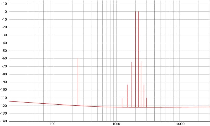
The sidebands are spaced at the f2-f1 gap on either side of our fundamental frequencies. The amplitude of the sidebands decreases as they move away from the fundamental frequencies, eventually becoming low enough that they don’t matter significantly. Audio components that exhibit high levels of IMD add significant amounts of unwanted audio information to the signal sent to the speakers.
Distortion at All Frequencies
What’s difficult to remember about examples of distortion is that they happen at all frequencies. As we mentioned, music isn’t made up of single notes, so there is unwanted content added across the entire frequency spectrum. Here’s a small example of four frequency pairs and their associated intermodulation distortion characteristics.
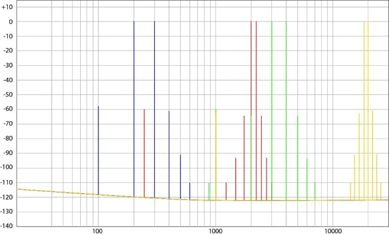
The graph above is both under- and over-exaggerated. We’d never see full-amplitude audio content at 19 and 20 kHz. However, the graph only shows the IMD distortion for each pair of frequencies and not the distortion that would be added between the differently colored pairs. The graph would be awash with unwanted audio content. That’s the issue with IMD – every frequency interacts with every other frequency to add information not in the original recording.
Measuring IMD on our Example Amplifiers
As we’ve been doing throughout this series, we’ll measure IMD levels on a pair of amplifiers to give you a real-world look at the difference in their performance and, ultimately, their quality. For this article, we have the same low-quality Class AB amplifier and a high-end unit of similar topology. The Class D amp we’ve been using performs well in this test, but it’s on loan to someone for a few weeks.
We’ll start with the excellent amplifier and look at a few numbers.
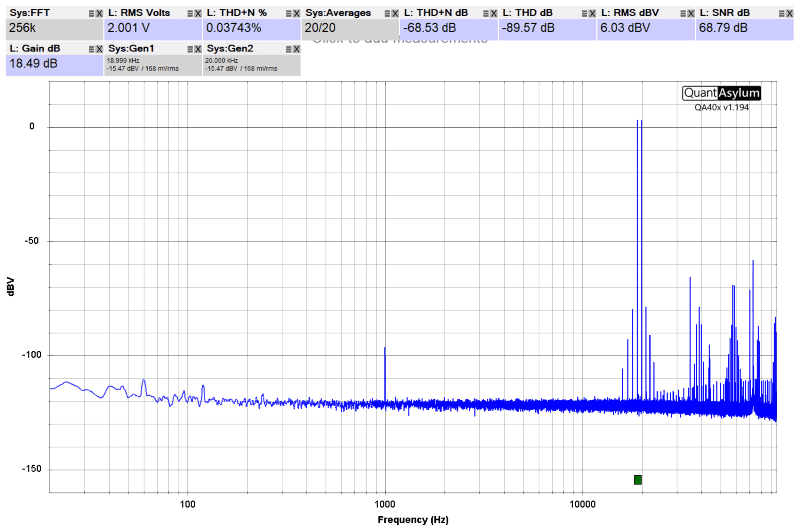
We will use the International Telecommunication Union (ITU) standard test for measuring IMD products for these tests. This test uses a pair of tones – one at 19 kHz and the second at 20 kHz. We’ll focus on the f2-f1 and sideband frequencies. However, it’s worth noting that the f1+f2 frequencies are crucial in broadcast scenarios.
Our measurement above shows the 19- and 20-kHz tones playing a summed level of just over 2.0 volts. We can start to evaluate the amplifier’s performance by looking at the amplitude of the f2-f1 frequency. In this case, it’s at a level of -97 dBV. That’s over 100 dBV lower or quieter than the test tones.
Next, we can observe the amplitude of the sidebands beside the 19- and 20-kHz tones. In this amplifier, those first sidebands are at -78 and -79 dBV and the second pair are at about -93 and -91 dB. The third pair are well below -100 dBV. This would be considered an exceptional performance.
Poor-Quality Amplifier Analysis
Let’s look at our reference example of a poorly designed amplifier. We’ve adjusted the levels to be nearly identical to those of the high-end amplifier.
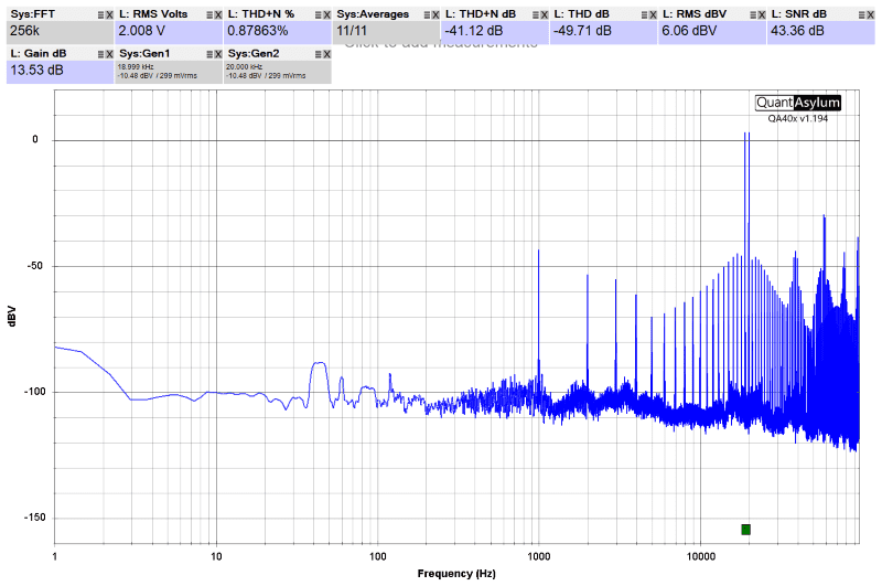
Let’s start with the f2-f1 frequency again. Here, we can see it’s at about -44 dBV. To put this into perspective, that’s about 6.31 millivolts or 0.00631 volts. The good amp produced this same frequency at an amplitude of 14.1 microvolts, or 0.0000141 volts. That’s 447 times more unwanted information added to the output signal.
Let’s see if we can extract anything numerical from the sidebands. The first, second, third and fourth sidebands are all at a level higher than -50 dBV. Further, we can see the sidebands out to the 14th on the low side before harmonics of the f2-f1 information overshadow them. It should go without saying that listening to the output of this amplifier would be dramatically different in terms of clarity and detail than the high-end solution.
The Warm Tube Sound
So, what does IMD sound like? If you’ve ever heard a home audio amplifier that uses vacuum tubes, you’ve likely experienced what many describe as a “warm” sound to the music. There’s some accentuation and blurriness of the lower midrange and midbass frequencies. Knowing how IMD adds lower-frequency distortion, this emphasis makes sense. However, it makes drum sounds sloppy and muddy, losing their dynamic properties.
There’s a significant difference between equalizing an audio system to produce more midbass or midrange and using equipment that adds audio information not present in the original recording. There’s nothing wrong with asking for your audio system to be calibrated to sound warm and rich through the midbass region – that’s a personal preference.
We will discuss crosstalk and how it affects imaging and staging in the following article. Until then, drop by a local specialty mobile electronics retailer and audition the different sound units, amplifiers, speakers and subwoofers they offer to make your car stereo sound magnificent.
More From Our “Amplifier Differences” Series
- Part 1: Frequency Response explores how amplifiers handle different frequencies and how this affects the sound. It discusses the ideal of uniform amplification across all frequencies and examines how real-world amplifiers compare, using specific models for illustration.
- Part 2: Noise delves into the noise that amplifiers can add to the audio signal, how it’s measured, and its impact on sound quality. It explains the signal-to-noise ratio and how different amplifiers manage noise, including the effect of amplifier size on noise performance.
- Part 3: Harmonic Distortion discusses the concept of harmonic distortion, how it affects sound quality, and the performance of different amplifiers in minimizing it. It also touches on the distinction between even- and odd-order harmonics.
- Part 4: Distortion Versus Power Level and Frequency examines how distortion levels in amplifiers change with power levels and frequencies, highlighting the differences between high-quality and low-quality amplifiers in handling distortion.
- Part 5: Intermodulation Distortion focuses on intermodulation distortion, how it’s measured, and its effect on sound quality. It contrasts the performance of different amplifiers in managing IMD.
- Part 6: Car Audio Amplifier Crosstalk addresses how crosstalk between channels in an amplifier can affect the stereo imaging and soundstage of car audio systems, impacting the overall listening experience.
