
Our Car Audio Masterclass series offers a comprehensive introduction to the essential concepts of car audio systems, covering everything from basic terminology to advanced measurement techniques. To learn more, check out the other articles in the series:
- Car Audio Masterclass 101.1 – Audio Basics: Learn key audio terms and concepts.
- Car Audio Masterclass 101.2 – Understanding Basic Electricity: Explore voltage, current, and resistance.
- Car Audio Masterclass 101.4 – Magnetism: Discover the role of magnetism in speakers.
- Car Audio Masterclass 101.5 – Direct and Alternating Current: Compare DC and AC currents.
- Car Audio Masterclass 101.6 – AC Calculations: Dive into AC waveform calculations.
- Car Audio Masterclass 101.7 – The Decibel: Learn about decibel measurements.
- Car Audio Masterclass 101.8 – Speakers, Power, and SPL: Understand speaker power and sound levels.
- Car Audio Masterclass 101.9 – Time and Frequency Domain Measurement: Explore frequency and time measurements.
- Car Audio Masterclass 101.10 – Digital Multimeter: Learn to use a multimeter in car audio.
Now that we’ve explained how electricity works and considered some basic equations to describe the math around quantifying the work done, we can start to assemble some basic electric circuits. This might be a flashback to grade 9 science class. Even if it isn’t, understanding power sources and loads and how they interact is crucial to understanding how everything from a speaker to a radio or amplifier works. This knowledge is not just theoretical, but it has practical applications in enhancing your car audio experience. Let’s dig in and examine some basic electric circuits and review the math on how different loads affect each other, making this knowledge not just interesting but also relevant and helpful.
What is an Electric Circuit?
Technically, an electric circuit is a closed path with a power source, a load, and conductors. As we discussed in the previous article, the amount of work done depends on the power source’s voltage and the load’s resistance.
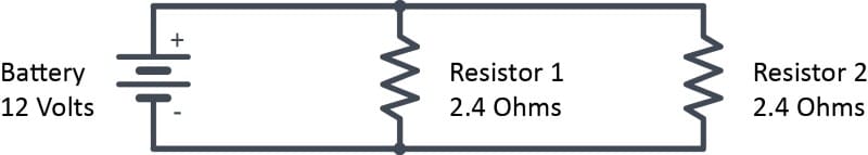
Here is a very basic electrical circuit:

This drawing above is called a schematic. This is a standard way of showing how electric devices are connected. The symbol on the left is a battery. If there were just a single large and single small horizontal line, it would be considered a power cell. The symbol on the right is a resistor. The black lines that connect the battery to the resistor are our conductors. We can assume that there is a connection where the lines touch a device like the battery or load. However, when lines cross or intersect, there isn’t necessarily a connection. To indicate a connection, we add a dot.
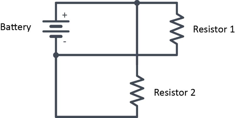
In the above schematic, the wire from the top of Resistor 2 is only connected to the top wire from the battery. Where it crosses the original lower wire, there is no connection.
The Function of a Circuit
If you are a level-10 geek like some of our staff members, Derek Muller’s video on the Veritasium YouTube channel explains a very different and more accurate way of understanding how electricity works. However, that’s too confusing for most, so we’ll continue with the moving electron model.
What’s crucial to understanding electric circuits is that there needs to be a complete path from the power source to the load and back. In Diagram 1, we have a connection from the positive side of the battery to the resistor (also called the load) and a separate connection from the negative side of the battery to the other side of the resistor. In our simple circuit model, electrons flow from the negative side of the battery through the load to the positive side.
Car Audio Circuit Examples
Let’s look at how a car audio amplifier connects to the vehicle battery. The positive connection on the amp goes to the positive connection on the battery. The ground (or negative) connection on the amp connects to the negative terminal on the battery. This negative connection is often done by connecting the amp to the vehicle chassis, which is connected to the negative side of the battery.
We can make some calculations about the function of the circuit if we know a few pieces of information about the battery and the resistor. To keep this automobile-related, let’s say we have a 12-volt battery. The load might be something like an incandescent headlight, so five ohms.
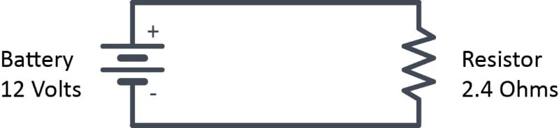
Knowing this information, we can calculate the current flowing in the circuit and the power dissipated in the load. The current calculation formula, explained in lesson 101.2, is I = V ÷ R. Substituting in our known values, we get 12 ÷ 2.4, which is five amps. We can also calculate the power dissipated in the load, the same as the work done. We’ll use the formula P = V² ÷ R, as we were given those values. Swapping in our 12-volt battery and five-ohm load, we get (12 x 12) ÷ 2.4, which works out to 60 watts.
Series Circuits
The next step in learning about electrical circuits involves understanding what happens when multiple loads are connected to the same power source. We can wire loads in two ways—series or parallel. How loads are wired changes how much voltage they get from the source (battery) and how much work they do. We’ll start with a series circuit, as it is the simplest to understand.
A series circuit implies that there is one single path through which current flows. It’s like a chain of loads with no branches.
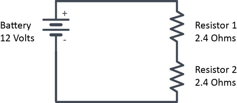
What matters the most about understanding loads in a series circuit is calculating the total resistance. Thankfully, this is simple. The individual resistances add together. So, for this example, the total resistance in the circuit is 2.4 + 2.4, which is 4.8 ohms.
We now have a very different load on the battery. First, let’s look at the total current in the circuit. The formula is I = V ÷ R, or 12 ÷ 4.8, which equals 2.5 amps. Given that we have twice the resistance, it makes sense that we have half the current. Suppose we want to know how much work each resistor is doing. In that case, we can calculate the power dissipated by each using the formula P = I² x R. With 2.5 amps of current flowing through each resistor, the power dissipated is (2.5 x 2.5) x 2.4, which equals 15 watts.
Power in Series Circuits
If you are paying attention, you might wonder why each resistor is only dissipating one-quarter of the energy as when there was a single resistor in the circuit. The answer is that the voltage from the battery is now split between the loads. We can calculate the voltage across each resistor by multiplying the resistance by the current. This is 2.4 times 2.5, which equals six volts.
This is another important takeaway from the series circuit. The voltage across each load is proportional to the ratio of its resistance to the total resistance in the circuit. The circuit in the image below will help to explain this.
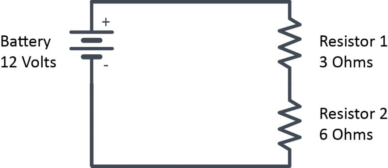
The first step in understanding this circuit is to calculate the total resistance. That’s easy. We add the values of each resistor. So, three plus six is equal to nine. The next step is to calculate the current flowing through the circuit. This can be done by dividing the supply voltage by the total resistance, 12 ÷ 9, or 1.33 amps. Next, we calculate the voltage across each load. That formula is V = I x R, or 1.33 x 3 and 1.33 times 6. This equals four and eight volts, respectively.
Power Calculations
If we measure the voltage across the battery, we will see 12 volts. We will see four volts if we measure the voltage across the three-ohm resistor. We will see eight volts if we measure the voltage across the six-ohm resistor. Kirchoff’s Voltage Law states that the sum of the voltage drops across loads in a circuit must equal the voltage across the source.
While doing the math, let’s look at the power dissipated by each load. The three-ohm resistor has four volts across it and 1.33 amps of current flowing through it, so that works out to P = V x I, 4 x 1.33, which is 5.32 watts. The six-ohm resistor has the same current flowing, but the wattage will be higher because the voltage is higher. The math is 8 x 1.33, or 10.64 watts.
These calculations are essential to car audio applications if we wire speakers with different impedances in series. This information also becomes essential as we discuss capacitors and inductors used in crossovers.
Parallel Circuits
The other way we can wire multiple loads together is called parallel. In this method, the loads are all connected directly to the power source terminals, which is the battery in our example.
What’s unique about this type of wiring is that there are two paths for current from the battery to flow. The electrons can leave the battery, pass through resistor 1, and then return to the positive terminal. Independently, additional electrons flow from the battery’s negative through resistor two and back to the battery.
Figuring out what’s happening in the circuit starts with calculating the net load on the power supply. The formula to calculate parallel resistance is a bit complicated.
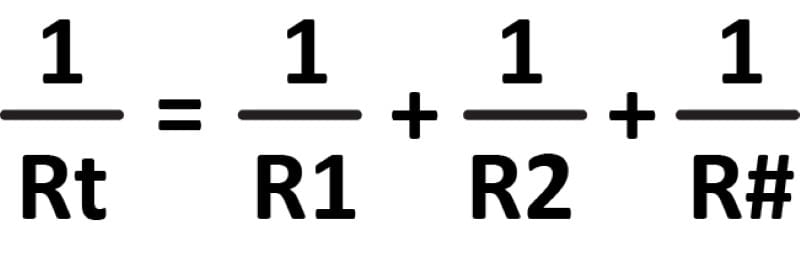
While it looks involved, it’s not too bad. First, Rt is the total resistance. R1, R1, and so on are the values of each resistor wired in parallel. The number of resistors is unlimited, so we used R# to indicate that.
Let’s use the resistance values in the original parallel circuit diagram of 2.4 ohms. The first step takes the inverse of that number, which is to say, divide one by 2.4, which equals 0.41666. You need to keep track of a few decimal places to ensure accurate results.
The next step is to add the two inverses together. This is as simple as adding 0.41666 to 0.41666. If we had a third resistor of the same value in the circuit, we’d add that value again. For now, we have 0.41666 plus 0.41666, which is 0.8333.
The last step is to take the inverse of the total. So, we divide one by 0.8333 to get 1.2 ohms.
Parallel Circuit Resistance Shortcuts
There are a few shortcuts we can use to calculate parallel resistances. If two equal resistances are wired in parallel, the resulting resistance is half of one of the resistances. So, two four-ohm speakers wired in parallel would be two ohms. If we have three resistors of the same value wired in parallel, the net resistance is 1/3 of the resistance of a single resistor. The pattern repeats for four, five, or more resistors.
We can summarize this shortcut by saying that the net resistance of multiple indentical loads in a parallel circuit is equal to the inverse of the number of loads times the value of one of the loads. For ten 100-ohm resistors in parallel, we would calculate 1/10 of 100, which equals 10. For five 25-ohm resistors in parallel, we calculate 1/5 of 25, which is five.
Let’s look at a second parallel circuit diagram.
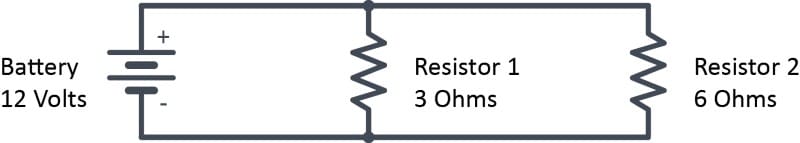
There are two ways to figure out what’s happening in this circuit. The easiest method is to calculate the current flowing through each resistor. We can do this because we know there is 12 volts applied across each resistor. So, for R1, I = V ÷ R, or 12 ÷ 3, which is four amps. For R2, the current is 12 ÷ 6 = 2 amps. We know that the current for each branch must come from a single power source, so we can add them together. The total current in the circuit is six amps.
Let’s check our logic by calculating the total resistance of the circuit. If we take the inverse of 3, we get 0.33333. If we take the inverse of 6, we get 0.16666. Next, we add those together to get 0.5. We finish by taking the inverse of that number to get 2. The net resistance in the circuit should be 2 ohms. If we use that value to calculate the current using I = V ÷ R, then 12 ÷ 2 is six. This matches our first calculations.
Power in Parallel Circuits
Now, let’s look at how much power each load dissipates. We use voltage and resistance as those values are provided to us. The formula will be P = V² ÷ R. For resistor one, the math is (12 x 12) ÷ 3, which works out to 48 watts. For the second resistor, the math is (12 x 12) ÷ 6, which is 24 watts. It makes sense that the higher value resistor produces less heat, as half as much current flows through it. The circuit consumes a total of 72 watts.
We can check this power number by calculating the total power of the circuit using the supply voltage and the total current. Our supply voltage is 12 volts, and the circuit draws six amps of current. Using P = V x I, we get 12 x 6, which equals 72.
Why Do I Need to Understand Electric Circuits?
We could go on and on with combinations of series and parallel wiring examples until the cows come home. This matters, especially in car audio, because of wiring subwoofers. People ask how to wire a pair of dual voice coil subwoofers to a specific impedance daily. As the expression goes, “Give a man a fish, and he’ll eat for a day. Teach a man to fish, and you feed him for a lifetime.” The Car Audio Masterclass series aims to bring consumer knowledge to an entirely new level. It will take a while, but you’ll understand how everything in your car audio system works once done. That will make you a better shopper, and you’ll end up with a stereo system that works and sounds better.
Our next article will look at the complex concept of magnetism.
